I have been a DIY enthusiast for some years now, in the past I have experience building the Elekit TU-8600, a Couple of Audio Note Kits, and refurbished the Lenco L75 Turntable based on PTP6. The article below is my experience in building the Sunvalley SV-EQ1616D phono equalizer. It’s been one of the hardest kits I have built as it is not just point-to-point but also because it has lots of electronics components crammed up within a small footprint.
I ordered the kit from VKmusic, Victor as always has always been the most helpful guy I know with Customer service and response par excellence. The Kit arrived from Canada to Dubai within 3 days. I was super excited to start building the kit, however, I knew I had to read the build guide carefully, study the sequence of the build and have lots of patience.
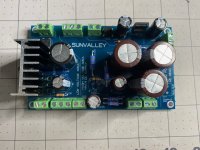
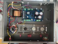
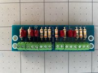
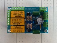
I started by taking stock of all the components, measured every resistor and capacitors to make sure the values were within range. Once this activity was completed, I knew I was ready to start the build. I followed the same sequence of assembly defined in the build guide. First, the power supply board received the resistors, the diodes, the capacitors, and the terminal blocks, followed by the input selector and the turnover select board.
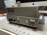
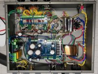
In my next step, I fixed the transformer, the fuse casing, the switches, the pilot lamp, and the potentiometer. The kit came with a 2 prong IEC male and I replaced it with a 3 prong Furutech IEC Male Inlet which I soldered the ground pin of the IEC to the ground point of the chassis. As I had with me an extra grounding post I replaced the one from the stock. Next, I fixed the lug plates, the tube sockets, and the power supply board and started with the point-to-point wiring, carefully cutting the lengths and making sure it's nicely organized. The stock RCA female jacks were somewhat fragile, so I decide to replace them with KLEI Perfect Harmony RCA Female Jacks. The input selector board followed next.
Soldering of the wires and resistors was a very delicate activity keeping in mind the color legend (blue for firm and orange for partial soldering). I remeasured the resistors, capacitors cut them to proper lengths before attaching them to the lug plates. Believe me, this is a patience job, take your time, check and double-check to assure that you are fixing at the right position. Make sure the legs of the capacitors, resistors are not shorted with other components. A simple mistake would be a real pain to troubleshoot and refix. The final piece was to fix the turnover select board. I was excited that at last after 5 days the kit was complete.
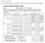
Testing: I popped in the solid-state rectifier (V4) with some old Shuguang 12AX7 tubes (V1, V2) and Mullard 12AU7 (V3) and started measuring the voltage. I was thrilled that my voltage measurement was within range for the V1, V2, however, my joy was short-lived when I tested the V3 cathode terminal I was getting an abnormal voltage measure in the 256V range when the baseline is about 135V. All other voltages (Heater, MC) were within range. I knew at this stage that something was wrong, so I immediately send Victor my readings and within minutes I get a response to check the wiring in the area. As I was already tired and it was a late evening I wrapped up and retired for the night. The next day I started troubleshooting by checking each and every component and solder points meticulously and within hours I was able to pinpoint the issue. Surprisingly the issue was with a black cable that did not show continuity, desoldering the cable and installing another one solved the issue. All measurements were within ranges.
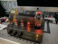
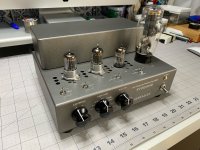
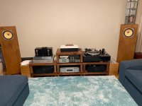
Now the fun part: I replaced the test tubes with Telefunken NOS 12AX7 (V1, V2) and Telefunken NOS 12AT7 (V3) along with the rectifier tube PSVANE WE 274B. Connected the power, put on an LP, set the switches on the phono stage, and pumped up the volume. Immediately I could feel the day and night difference compared to my existing phono stage (ANK L3 phono stage). The soundstage got bigger with tighter bass, amazing 3D imaging, the instrument separation and the details in the music was something I had never felt or heard before. I listened continuously for over 4 hours I was completely immersed in the music giving me goosebumps as I played LP’s after LP’s.
I can never thank Victor enough for the joy this kit has given me. My Precious Jazz collection has come to life. Thank you Victor once again.
Pictures of my build attached
I ordered the kit from VKmusic, Victor as always has always been the most helpful guy I know with Customer service and response par excellence. The Kit arrived from Canada to Dubai within 3 days. I was super excited to start building the kit, however, I knew I had to read the build guide carefully, study the sequence of the build and have lots of patience.
I started by taking stock of all the components, measured every resistor and capacitors to make sure the values were within range. Once this activity was completed, I knew I was ready to start the build. I followed the same sequence of assembly defined in the build guide. First, the power supply board received the resistors, the diodes, the capacitors, and the terminal blocks, followed by the input selector and the turnover select board.
In my next step, I fixed the transformer, the fuse casing, the switches, the pilot lamp, and the potentiometer. The kit came with a 2 prong IEC male and I replaced it with a 3 prong Furutech IEC Male Inlet which I soldered the ground pin of the IEC to the ground point of the chassis. As I had with me an extra grounding post I replaced the one from the stock. Next, I fixed the lug plates, the tube sockets, and the power supply board and started with the point-to-point wiring, carefully cutting the lengths and making sure it's nicely organized. The stock RCA female jacks were somewhat fragile, so I decide to replace them with KLEI Perfect Harmony RCA Female Jacks. The input selector board followed next.
Soldering of the wires and resistors was a very delicate activity keeping in mind the color legend (blue for firm and orange for partial soldering). I remeasured the resistors, capacitors cut them to proper lengths before attaching them to the lug plates. Believe me, this is a patience job, take your time, check and double-check to assure that you are fixing at the right position. Make sure the legs of the capacitors, resistors are not shorted with other components. A simple mistake would be a real pain to troubleshoot and refix. The final piece was to fix the turnover select board. I was excited that at last after 5 days the kit was complete.
Testing: I popped in the solid-state rectifier (V4) with some old Shuguang 12AX7 tubes (V1, V2) and Mullard 12AU7 (V3) and started measuring the voltage. I was thrilled that my voltage measurement was within range for the V1, V2, however, my joy was short-lived when I tested the V3 cathode terminal I was getting an abnormal voltage measure in the 256V range when the baseline is about 135V. All other voltages (Heater, MC) were within range. I knew at this stage that something was wrong, so I immediately send Victor my readings and within minutes I get a response to check the wiring in the area. As I was already tired and it was a late evening I wrapped up and retired for the night. The next day I started troubleshooting by checking each and every component and solder points meticulously and within hours I was able to pinpoint the issue. Surprisingly the issue was with a black cable that did not show continuity, desoldering the cable and installing another one solved the issue. All measurements were within ranges.
Now the fun part: I replaced the test tubes with Telefunken NOS 12AX7 (V1, V2) and Telefunken NOS 12AT7 (V3) along with the rectifier tube PSVANE WE 274B. Connected the power, put on an LP, set the switches on the phono stage, and pumped up the volume. Immediately I could feel the day and night difference compared to my existing phono stage (ANK L3 phono stage). The soundstage got bigger with tighter bass, amazing 3D imaging, the instrument separation and the details in the music was something I had never felt or heard before. I listened continuously for over 4 hours I was completely immersed in the music giving me goosebumps as I played LP’s after LP’s.
I can never thank Victor enough for the joy this kit has given me. My Precious Jazz collection has come to life. Thank you Victor once again.
Pictures of my build attached
Attachments
Nice work! I also just finished and can relate very much to your experience. I don’t believe i have any bad solder joints but i did completely miss installing the blue wire until i found my voltage readings were way off. I think i will go back through and test continuity for all the point to point because if the eq circuit is off you might not see that in the voltage test points and it might be a subtle audio difference. There’s just so much room for error.
Thank You Odamone, the most important thing i learnt from the project is to have tons of patience and to make sure every component is in the right place and joint is soldered properly and inspected. Would love to see the voltage readings from your build. I am attaching mine below
Attachments
Thanks for synopsis of your kit building experience Rwind. It took me more than a week to complete mine. I made 2 mistakes but neither was critical. The first was I didn't understand instructions on page 8 dealing with interconnecting the terminal blocks like Lego pieces. The second was on page 12 - installing the V1, V2 tube sockets using the same bolts as the 1L2P lug plates. I found P1L1 and P2R1 voltages to be under 162v. Victor says 162v is with the Gold Lion tubes and 10% difference is OK I used Line Magnetic 12AX7s from another amp and measured 150v. I wonder if anyone encountered the same?
Lastly, where is the RIAA network? Is it comprised of the Caps and Resistors wired point to point on the tube pins? Thanks.
Lastly, where is the RIAA network? Is it comprised of the Caps and Resistors wired point to point on the tube pins? Thanks.
Thanks for the feedback. Reassuring that I did not miswire something to the V1 & V2 tubes. Also wondering what settings you are using to play modern 12" LPs. According to Operations 2 & 3 page images that Victor posted, the Rolloff switch is set to ON for LP and the Rolloff potentiometer is set to RIAA (pointing up). When I set the Rolloff switch to FLAT there is a level boost between 8 and 10 kHz.
I made a few mistakes. Forgot the blue wire, installed the turnover select dial long before i was supposed to (just annoyingly in the way), some orange half solder joints somehow got soldered shut before all was in place, and installed the second vcap backwards (not sure why the orientation matters but Victor said it did). I too would like to know where the RIAA eq is. Rwind, i want to retake measurements and will share here when I do. Right now im trying to break it in as the bass is not as tight as I’d like.
Ray i read in an early victor post that the flat eq is only for sp records. It certainly adds a ton of top end clarity - almost like adding a super tweeter.
My records are set to eq on, riaa, riaa rolloff.
Ray i read in an early victor post that the flat eq is only for sp records. It certainly adds a ton of top end clarity - almost like adding a super tweeter.
My records are set to eq on, riaa, riaa rolloff.
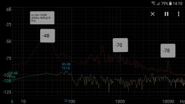
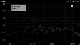
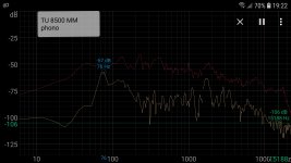
Thanks for info Odamone. When you say "eq on" are you referring to the Rolloff switch which is either FLAT or ON? Victor assures this switch should be set to FLAT for modern 12 inch LP records. I decided to use an Android spectrum analyzer app and a Dayton Audio calibrated mic with my smartphone to measure the frequency response of a music track that I found had alot of high frequency energy. I then did the same using the phono section of my Elekit TU 8500 preamp. I used the Lundahl SUT and MM inputs in both cases. Screenshots attached (I hope). These aren't accurate freq responses due to room effects and music is not the same as a frequency sweep or pink noise. Nevertheless the FR of the TU8500 shows a decline from 2 kHz out to 10 kHz while the FR of the SV stays flat out to 10 kHz. I think my conclusion of an elevated high frequency response is incorrect. Its just that I have never heard the higher frequencies that are on my records with any previous phono preamp. Most of my LPs (1970s) sound a bit soft and muted but now they are dynamic and clear. I hear instruments I never heard before. I'm looking forward to discovering new revelations in the coming weeks.
Attachments
Thanks for the feedback. Reassuring that I did not miswire something to the V1 & V2 tubes. Also wondering what settings you are using to play modern 12" LPs. According to Operations 2 & 3 page images that Victor posted, the Rolloff switch is set to ON for LP and the Rolloff potentiometer is set to RIAA (pointing up). When I set the Rolloff switch to FLAT there is a level boost between 8 and 10 kHz.
I have played some old jazz Japanese records and i am using the rolloff switch to on and rolloff to max. This has reduced the surface noise and the sound is warm and delicate. I like it this way. I have not experimented with new records yet but will do it this weekend, will report my findings.
Ray77 click here and scroll down the the images under operation manual 2&3. There is says, fir roll off, LP is on and SP is flat. I don’t know what an SP is but perhaps a shellac 78?
So my thinking is that the RIAA standard is achieved with turnover set to RIAA and rolloff set to on and RIAA (12 o’clock).
So my thinking is that the RIAA standard is achieved with turnover set to RIAA and rolloff set to on and RIAA (12 o’clock).
Thanks Odamone. I read same and think you are correct. According to RIAA playback curve there should be a 19 dB boost at 30 Hz relative to level at 1000 Hz and a 14 dB attenuation at 10,000 Hz. I fed line level test tones into phono 1 (MM) with Rolloff switch = FLAT and used spectrum analyzer app, etc. to record the levels at each frequency. I measured +22 dB at 30 Hz (pretty close as I use a subwoofer that might have added additional boost). At 10 kHz I measured -8 dB (a bit hot). I didn't get a chance to remeasure with Rolloff = ON and Rolloff Pot centered but there was definitely further attenuation (perhaps to specified -14 dB). These settings sound closer to what I was hearing with the Elekit TU 8500 phono section. I've attached another screenshot. I'll experiment with using the High Gain setting in MM mode to compensate for additional HF attenuation of the Rolloff switch.