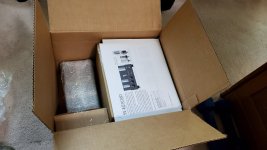
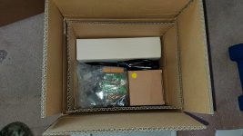
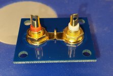
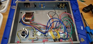
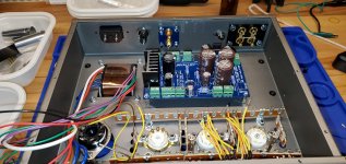
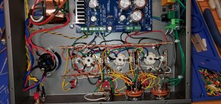
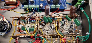
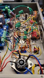
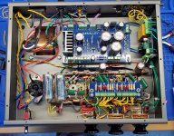
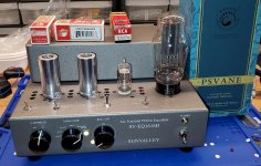
I just finished building my SV-EQ1616D All Purpose Phono Equalizer and wanted to share some photos.
I have lots of photos so I'll spread them across several posts. I'm no expert so I'm not suggesting that you follow my technique to build yours. I'm just sharing photos, good or bad technique and all.
I do welcome suggestions about improving my technique because I want to improve my skills since I have been bitten by the kit-building bug.
Attachments
-
 20200810_125941.jpg754.3 KB · Views: 797
 -
 20200810_131152.jpg866.4 KB · Views: 780
 -
 20200812_120446.jpg686.8 KB · Views: 782
 -
 20200812_120612_sm.jpg353.2 KB · Views: 750
 -
 20200812_120708_sm.jpg248.8 KB · Views: 750
 -
 20200813_192840_sm.jpg407.1 KB · Views: 290
 -
 20200814_192504.jpg905.3 KB · Views: 273
 -
 20200814_192513.jpg955.7 KB · Views: 281
 -
 20200814_195050.jpg970.1 KB · Views: 320
 -
 20200814_195604.jpg920.6 KB · Views: 340
Next set of photos.
Attachments
-
 20200816_114906_sm.jpg655.9 KB · Views: 350
 -
 20200816_135958.jpg963.1 KB · Views: 265
 -
 20200816_181440.jpg598.3 KB · Views: 253
 -
 20200816_223900.jpg997.5 KB · Views: 261
 -
 20200817_162725.jpg636.2 KB · Views: 258
 -
 20200818_084551.jpg992.7 KB · Views: 274
 -
 20200818_084705_sm.jpg658.7 KB · Views: 303
 -
 20200818_093524.jpg849.9 KB · Views: 282
 -
 20200818_144245_sm.jpg534.3 KB · Views: 308
 -
 20200818_165934_sm.jpg743.6 KB · Views: 386
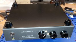

SV-EQ1616D
Hi:
Love the pictures and the construction steps.
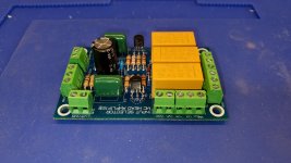
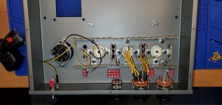
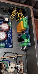
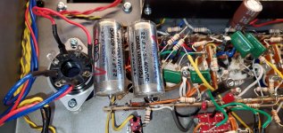
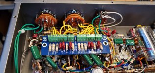
I do not agree with the unbypassed diodes , 1N4007's or UF4007's , in the picture of the solid state rectifier shown. There should a buffer across each diode , .01 mfd 1000 volt mylars and at least a 470k resistor? This according to the ARRL Radio Amateurs Handbook. This is to supress diode switching noise and to protect the diodes.
BTW Loved the article by Herb Reichert in Stereophile 11/20.
Can I get a schematic please ?
Thank You
Ed Lipman
Hi:
Love the pictures and the construction steps.
I do not agree with the unbypassed diodes , 1N4007's or UF4007's , in the picture of the solid state rectifier shown. There should a buffer across each diode , .01 mfd 1000 volt mylars and at least a 470k resistor? This according to the ARRL Radio Amateurs Handbook. This is to supress diode switching noise and to protect the diodes.
Thanks Ed. To be honest, I have never used that solid state rectifier. I just built it because it was in the kit. I have only used the Psvane WE284B tube.
I just finished the kit, and in measuring the voltage it is way high on two pins, 2V. All the others are near exactly what is in the build instructions. Any ideas about what might be the issue? Victor suggested that I simply remove and re-solder the resisters and caps that are in that circuit. Does anyone know if this is a known issue, that is, a bad, poorly soldered or misplaced resistor would cause this?
What are the conditions of your tubes? That could play a major factor in readings in my experience. Btw I agree with Victor, resolder what you can. Also use solid state rectifier first to save your rectifier tube. There is mention in manual of voltage difference if using solid state rectifier so keep that in mind.
Last edited:
Thanks for the response. The tubes are new, came with the set. And I did measure using the solid state rectifier for the very reason that I wanted to save the rectifier tube! I've tried to trace what the two points on tube have in common. I thought maybe the 0.1uf 450v capacitor that is mounted nearby. Do you have an idea of where the power for those two points come from?
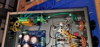
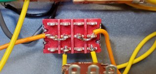
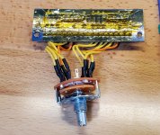
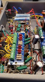
PCB terminal blocks on the PCBs
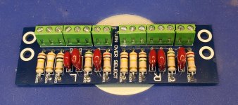
I noticed you did same as me with mounting the terminal blocks on the 3 printed circuit boards. On page 8 of assembling manual there are red U shaped marks indicating "connection". Even with the illustration on the left side of page I did not twig to the concept that the blocks interconnect like Lego blocks. Even though it doesn't affect the sound, I de-soldered the blocks and interconnected them. I do like the way you organized the wiring. After several weeks, what are your impressions wrt the sound?
I just finished building my SV-EQ1616D All Purpose Phono Equalizer and wanted to share some photos.
I have lots of photos so I'll spread them across several posts. I'm no expert so I'm not suggesting that you follow my technique to build yours. I'm just sharing photos, good or bad technique and all.
I do welcome suggestions about improving my technique because I want to improve my skills since I have been bitten by the kit-building bug.
I noticed you did same as me with mounting the terminal blocks on the 3 printed circuit boards. On page 8 of assembling manual there are red U shaped marks indicating "connection". Even with the illustration on the left side of page I did not twig to the concept that the blocks interconnect like Lego blocks. Even though it doesn't affect the sound, I de-soldered the blocks and interconnected them. I do like the way you organized the wiring. After several weeks, what are your impressions wrt the sound?