Here is the extracted from ELEKIT Voice October 21, 2019 to interview Mr Y Fujita
TU-8800 is the Greatest masterpiece in history of ELEKIT
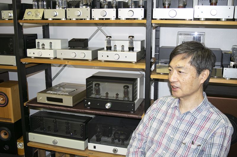
Mr Y. Fujita, Designer of TU-8800
Interviewer : The new TU-8800 is an amplifier that uses KT88 and has a slightly higher power than TU-8200R. Are there any new functions in TU-8800?
Mr Y. Fujita: By switching bias circuit and B power supply voltage ( power mode switch, HIGH-MID-LOW) , the output tube can now be replaced.

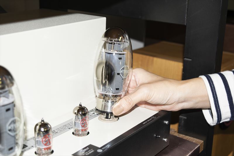
If you turn off the power mode, there is also the pleasure of trying a small output tube, such as 6V6. A powerful tube in a low power mode can be used to save power and reduce the burden on the output tube.
Interviewer : I see, the range of tubes that can be replaced has expanded further. Is the output mode switching fuction well received in TU-8200 still available?
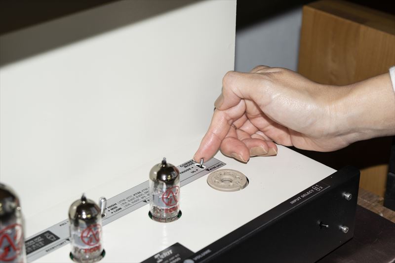
Mr Y. Fujita : Of course. With TU-8800, the UL (ultra linear) connection and triode connection can be switched with a switch, so you can enjoy the difference in sound more easily.
Triode and pentode configurations are 2 most common modes in audio vacuum tube amplifiers.
Pentode mode provides high efficiency and power, but some audio enthusiasts believe triode mode surpasses pentode mode in sound quality.
Pentode tubes can work as triode tubes by changing the external connection. Adding an SG tap to the output transformer enables an
intermediate operation- UL (Ultra-Linear) mode. In UL mode high efficiency similar to Pentode mode may be obtained and similar in sound
quality of triode mode. UL is the best mix of the advantages of triode and pentode modes.
In TU-8800, TRIODE mode and UL mode can be selected by the Connection Mode SW on top of the amp chassis.
Interviewer: The “Active Auto Bias” circuit started with the TU-8200. What is the difference in operation from the conventional bias circuit?
Mr Y Fujita: Generally, there are two methods for biasing vacuum tubes.
One is a “cathode bias” method that uses the voltage drop of the cathode resistance as the bias voltage. It is also called “self-bias” because the number of parts is minimal and simple, and even if there is an individual difference in the vacuum tube due to feedback by the cathode current, it balances in a good point. However, the cathode resistance consumes a lot of power and generates a lot of heat, so there is a disadvantage that you must change the resistance value if you want to replace it with another one with different characteristics.
The other is a `` fixed bias '' method that gives a constant negative voltage from the bias power supply to the control grid, and it is troublesome because it is necessary to manually adjust the bias voltage according to the individual difference of the vacuum tube, but conversely It can be adjusted to other vacuum tubes by adjustment. "... means that if you detect the cathode current with low loss and automatically adjust the bias voltage to keep it constant, you can make a perfect bias circuit" • Auto bias circuit.
The conventional "self-bias" is passive (passive) auto-bias, while it is active (active), so we named it like this.
Interviewer: The ripple filter circuit of the B power supply is also separate on the left and right in the TU-8800.
Mr Y. Fujita: It is a ripple filter that uses power MOSFETs, which is quite familiar with the TU series. In a vacuum tube amplifier, it is common to use a choke transformer to reduce the ripple of the B power supply.
However, the choke transformer is a big pain (laughs) , "heavy", and "high cost". I decided to use it from TU-879, thinking that power semiconductors are now widely available and cheaper.
Since the choke transformer is expensive, unless it is a very high-end machine, the left and right channels are often shared by a single unit. However, with a MOSFET, a ripple filter can be installed on each of the left and right at a low cost. By doing so, I was able to improve the separation between the left and right.
Interviewer: I was also interested in the TU-8200, but there are parts of the board where diagonal patterns are continuous. What is this?
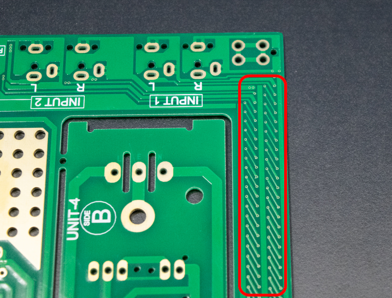
Mr Y. Fujita: The input line from the input jack to the volume via the input selector switch. The input line is susceptible to noise from the outside, so you have to wire a long distance from the jack on the back to the front where the volume and the first stage tube are. Counter measures are easy with electrostatic noise alone, but magnetic noise is not easy on the board. Magnetic noise leaks from the transformer, so you should try to pick it up as much as possible. “Twisted pair”, which combines two wires together, is effective as a countermeasure against electromagnetic noise, but it was also effective on the board after repeated experiments on the board.
Interviewer: Was that a twisted pair? By the way, are there many wires coming out of the output transformer?
Mr Y. Fujita: Actually, I'm applying a cathode feedback to the output tube. The blue and white wires are the tertiary winding for that.
Interviewer: If there are other minor improvements that aren't conspicuous.
Mr Y. Fujita: I wonder if relays were used to switch between speakers and headphones.
Since the power of this amplifier is high, I thought that it would be "what is it" to route the line back and forth to the headphone jack on the front side, so I examined the electrical resistance and contact resistance of the board pattern. As a result, I found it more advantageous to place a relay near the output terminal and switch with it.
If it is an ordinary relay, the relay contacts will come back when the power is turned off while listening to headphones, and a playback sound will be emitted from the speaker for a moment, so a 2-winding latching relay is used. Then, the power switch has been a toggle switch so far, but this time we have adopted a double push type.
Interviewer: Do you have any back stories?
Mr Y. Fujita: Yeah , when I asked for a prototype of the output transformer, I asked my usual transformer manufacturer, "Isn't you going to use Orient for the core and OFC (oxygen-free copper) for the winding?" "I basically use Orient Core and OFC ..." and "I'm so sorry!" So, in fact, TU-8200 series, 8600 series and so on. Anyway, I thought the quality was high (laughs).
In addition, this time we adopted the Takman product, which is popular among audiophiles.
Interviewer: It ’s a collection of small efforts. Thank you very much for today.

TU-8800 is the Greatest masterpiece in history of ELEKIT
Mr Y. Fujita, Designer of TU-8800
Interviewer : The new TU-8800 is an amplifier that uses KT88 and has a slightly higher power than TU-8200R. Are there any new functions in TU-8800?
Mr Y. Fujita: By switching bias circuit and B power supply voltage ( power mode switch, HIGH-MID-LOW) , the output tube can now be replaced.
If you turn off the power mode, there is also the pleasure of trying a small output tube, such as 6V6. A powerful tube in a low power mode can be used to save power and reduce the burden on the output tube.
Interviewer : I see, the range of tubes that can be replaced has expanded further. Is the output mode switching fuction well received in TU-8200 still available?
Mr Y. Fujita : Of course. With TU-8800, the UL (ultra linear) connection and triode connection can be switched with a switch, so you can enjoy the difference in sound more easily.
Triode and pentode configurations are 2 most common modes in audio vacuum tube amplifiers.
Pentode mode provides high efficiency and power, but some audio enthusiasts believe triode mode surpasses pentode mode in sound quality.
Pentode tubes can work as triode tubes by changing the external connection. Adding an SG tap to the output transformer enables an
intermediate operation- UL (Ultra-Linear) mode. In UL mode high efficiency similar to Pentode mode may be obtained and similar in sound
quality of triode mode. UL is the best mix of the advantages of triode and pentode modes.
In TU-8800, TRIODE mode and UL mode can be selected by the Connection Mode SW on top of the amp chassis.
Interviewer: The “Active Auto Bias” circuit started with the TU-8200. What is the difference in operation from the conventional bias circuit?
Mr Y Fujita: Generally, there are two methods for biasing vacuum tubes.
One is a “cathode bias” method that uses the voltage drop of the cathode resistance as the bias voltage. It is also called “self-bias” because the number of parts is minimal and simple, and even if there is an individual difference in the vacuum tube due to feedback by the cathode current, it balances in a good point. However, the cathode resistance consumes a lot of power and generates a lot of heat, so there is a disadvantage that you must change the resistance value if you want to replace it with another one with different characteristics.
The other is a `` fixed bias '' method that gives a constant negative voltage from the bias power supply to the control grid, and it is troublesome because it is necessary to manually adjust the bias voltage according to the individual difference of the vacuum tube, but conversely It can be adjusted to other vacuum tubes by adjustment. "... means that if you detect the cathode current with low loss and automatically adjust the bias voltage to keep it constant, you can make a perfect bias circuit" • Auto bias circuit.
The conventional "self-bias" is passive (passive) auto-bias, while it is active (active), so we named it like this.
Interviewer: The ripple filter circuit of the B power supply is also separate on the left and right in the TU-8800.
Mr Y. Fujita: It is a ripple filter that uses power MOSFETs, which is quite familiar with the TU series. In a vacuum tube amplifier, it is common to use a choke transformer to reduce the ripple of the B power supply.
However, the choke transformer is a big pain (laughs) , "heavy", and "high cost". I decided to use it from TU-879, thinking that power semiconductors are now widely available and cheaper.
Since the choke transformer is expensive, unless it is a very high-end machine, the left and right channels are often shared by a single unit. However, with a MOSFET, a ripple filter can be installed on each of the left and right at a low cost. By doing so, I was able to improve the separation between the left and right.
Interviewer: I was also interested in the TU-8200, but there are parts of the board where diagonal patterns are continuous. What is this?
Mr Y. Fujita: The input line from the input jack to the volume via the input selector switch. The input line is susceptible to noise from the outside, so you have to wire a long distance from the jack on the back to the front where the volume and the first stage tube are. Counter measures are easy with electrostatic noise alone, but magnetic noise is not easy on the board. Magnetic noise leaks from the transformer, so you should try to pick it up as much as possible. “Twisted pair”, which combines two wires together, is effective as a countermeasure against electromagnetic noise, but it was also effective on the board after repeated experiments on the board.
Interviewer: Was that a twisted pair? By the way, are there many wires coming out of the output transformer?
Mr Y. Fujita: Actually, I'm applying a cathode feedback to the output tube. The blue and white wires are the tertiary winding for that.
Interviewer: If there are other minor improvements that aren't conspicuous.
Mr Y. Fujita: I wonder if relays were used to switch between speakers and headphones.
Since the power of this amplifier is high, I thought that it would be "what is it" to route the line back and forth to the headphone jack on the front side, so I examined the electrical resistance and contact resistance of the board pattern. As a result, I found it more advantageous to place a relay near the output terminal and switch with it.
If it is an ordinary relay, the relay contacts will come back when the power is turned off while listening to headphones, and a playback sound will be emitted from the speaker for a moment, so a 2-winding latching relay is used. Then, the power switch has been a toggle switch so far, but this time we have adopted a double push type.
Interviewer: Do you have any back stories?
Mr Y. Fujita: Yeah , when I asked for a prototype of the output transformer, I asked my usual transformer manufacturer, "Isn't you going to use Orient for the core and OFC (oxygen-free copper) for the winding?" "I basically use Orient Core and OFC ..." and "I'm so sorry!" So, in fact, TU-8200 series, 8600 series and so on. Anyway, I thought the quality was high (laughs).
In addition, this time we adopted the Takman product, which is popular among audiophiles.
Interviewer: It ’s a collection of small efforts. Thank you very much for today.
Last edited: