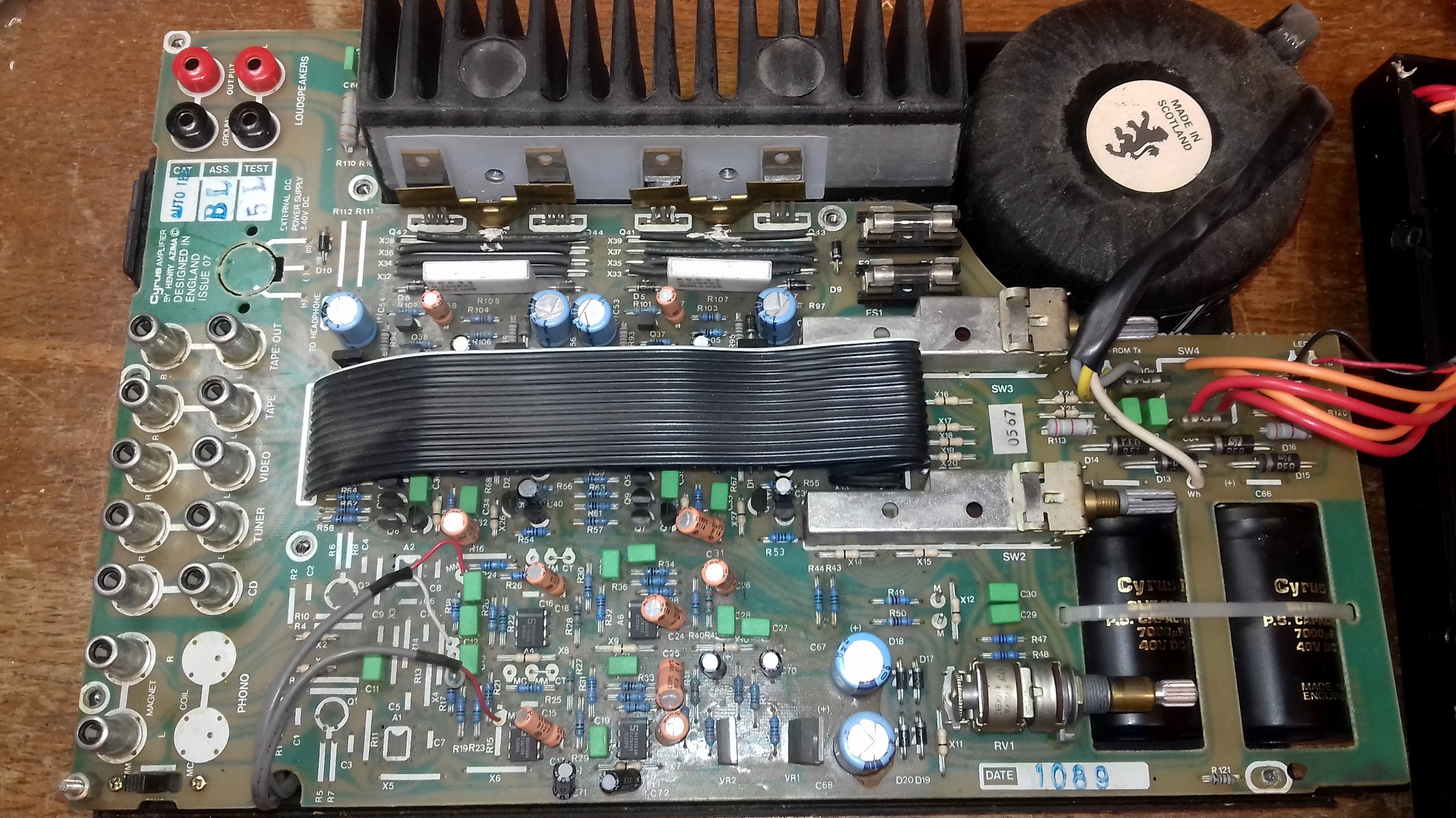
Following up on all this, I bypassed R43 and R44 today and while it makes the amp technically usable with lower impedance cans, the volume range is now too small and requires taming the input signal from my pre-amp capable DAC. This isn't how I'd like to keep it though.
Can anyone assist me with the formulas for how this circuit works? What I mean by that is that I would like to replace the 220 ohm resistors with an L-pad to reduce the output without increasing output impedance, but I need to know how to factor the 3.3 ohm resistors into my calculations. So two questions:
1) Am I correct in assuming that they are added in series AFTER the 220 ohm resistor and depending on the jumper setting?
2) Has anyone measured the voltage before the 220 ohm resistor? What are we starting with before the attenuation of the resistors? I forgot to measure this when I had the lid off today and I'm hoping to not have to dismantle it again for measurements if I can avoid it.
Following up on all this, I bypassed R43 and R44 today and while it makes the amp technically usable with lower impedance cans, the volume range is now too small and requires taming the input signal from my pre-amp capable DAC. This isn't how I'd like to keep it though.
If your DAC has a built-in pre-amp then you should be able to adjust output volume. The input sensitivity of the TU-8200 is quite average, if you drive it from a standard 2V DAC output then the volume range will be limited, but this is not a 8200 specific problem. Old amps tended to have even higher sensitivity as the output voltage of phono pre-amps, tape decks and tuners were way below 1V.
Output signal attenuation is fine with a solid state power amp but is a bad idea with SET amps that have limited output voltage and start distorting quickly. What you will end up with is high distortion and clipping even at medium volumes.
Nope. If you built the amp then you should have the manual. The schematics on page 19 show that the OPT output is terminated with 4x3.3 Ohm resistors in series (13.2 Ohms in total) when speakers are disconnected. The 220 Ohm resistors are between this resistor ladder and the phones. Whatever value you use instead, it will always be added to the output impedance with headphones.(...)
1) Am I correct in assuming that they are added in series AFTER the 220 ohm resistor and depending on the jumper setting?
2) Has anyone measured the voltage before the 220 ohm resistor? What are we starting with before the attenuation of the resistors?
I already wrote that the you get 1.5-2V output level at the lowest (1/4 level) jumper setting if you bypass the 220 Ohm resistors (or you measure the output voltage without phones).
To clarify my question about the resistors, I think you've confirmed my thinking, but would like to double-check.
Having built the amp and checking the circuit diagram, my understanding is that the 4x3.3 ohm resistors (or as many of them as are included in the circuit by the output jumpers) will be added to the circuit in addition to the 220 ohm resistors.
In other words, on 1/4 output with an unmodified build, the output impedance is 233.2 ohms. If I then changed the 220 resistors to 10 ohm resistors (for an example) then the output impedance on the 1/4 output setting would become 23.2 ohms. Is that correct?
To put it another way, I'm trying to confirm if the 3.3 ohm resistors are being used as a simple additional load or if they are working as a voltage divider. If a voltage divider, I may need to think differently about what values to use in place of the 220 ohm resistors.
As you can probably tell, I am new to making modifications of this nature despite having built quite a few amps and understanding the basics - this is stretching my knowledge so I appreciate the support!
The ladder is a voltage divider. The amp itself has a few Ohms output impedance even without the resistors. At any jumper setting, the output impedance is between 3 and 10 Ohms then you need to add 220 Ohms or whatever value you use to get the total value.
Your assumption with the 10 Ohm resistors is not accurate but more or less correct.
You can try to decrease the value of those 3.3 Ohm resistors that are connected to the ground if you need even lower output voltage, but as I wrote, it will introduce distortion quickly.
Your assumption with the 10 Ohm resistors is not accurate but more or less correct.
You can try to decrease the value of those 3.3 Ohm resistors that are connected to the ground if you need even lower output voltage, but as I wrote, it will introduce distortion quickly.
Hello,
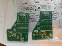
I built TU-8500 and thoroughly enjoyed the whole process and got TU-8200 Kit from eBay and to my surprise, Unit 8 board is not there which is similar to Unit 7 but Unit 7 PCB caters 100v and 200v only and Unit 8 actually cater 115v and 230v. And, I need 230v to use safely.
Is it possible to get Unit 8 PCB only? If not, can transformer wire solder directly without going through Unit 8 PCB to be able to use in 230v environment?
Thank you for any suggestion and recommendation in advance.
Last edited:
Hi, I had the same problem. But my seller sent me the correct unit for free based on my request.
I guess official Elekit distributors like Viktor in Canada or Adam from getAudio | The Best Audio DIY Kits >> getAudio in Poland will help you.
I guess official Elekit distributors like Viktor in Canada or Adam from getAudio | The Best Audio DIY Kits >> getAudio in Poland will help you.
Hi, I had the same problem. But my seller sent me the correct unit for free based on my request.
I guess official Elekit distributors like Viktor in Canada or Adam from getAudio | The Best Audio DIY Kits >> getAudio in Poland will help you.
Thank you very much. TubeSoundAudio does not help if the product was purchased from them directly.

I will try Viktor and Adam if they can help.. Thanks for the suggestion..
Hi Decommo
If you bought your TU-8200R from ebay or Amazon, you will not have unit 8 inside the cartoon box.
The Export version has unit 8 (115V or 230V PCB) to protect the authorised dealers. It costs a lot of effort to translate the manual and effort to import the products.
If you bought your TU-8200R from ebay or Amazon, you will not have unit 8 inside the cartoon box.
The Export version has unit 8 (115V or 230V PCB) to protect the authorised dealers. It costs a lot of effort to translate the manual and effort to import the products.
Hi Decommo
If you bought your TU-8200R from ebay or Amazon, you will not have unit 8 inside the cartoon box.
The Export version has unit 8 (115V or 230V PCB) to protect the authorised dealers. It costs a lot of effort to translate the manual and effort to import the products.
Makes sense. I wish I knew this before buying from eBay and it is too late to return since it was opened and started building.
Any chance to get the PCB8 separately?
did not receive any email from you
It might be gone to spam folder. I just forwarded the email again and also sent you PM with my email address.
Almost done on TU8200R except PCB Unit 8 which I do not have one yet.
(Hello, @sharpi31 , if you no longer have one to offer, could you please at least let me know so I start looking for an alternative option?)
It took me about 12 hours for a novice like me. TU-8500 took me about 9 hours for comparison.
This is the second DIY Kit build (the first one was TU-8500). Here is the shot (I wish I took some more photos before putting them all together).
What I personally found is that it is at least one level harder than TU-8500 because there are 40 pin connectors (CN3 and CN4) that require fine soldering and careful of solders stuck together between pins. There were a couple of pins that solders stuck together so I had to remove excess solder using solder wick and re-do them.
Other than that, it was not too difficult and huge fun doing that. I now see why people praise Elekit Kit. The Kit is very well put together and made accessible to novice people like me.
And, love the compact size of the amp which only takes half-width of rack shelf so I can put another component on the same shelf. Shelf space is getting scarce so any space saving is greatly appreciated.
I am afraid that a phono preamp board would pick up a lot of magnetic and electrical noise in that amp.
Thank you for the info.
Dumb question to ask if you don't mind... Why does phono board would pick up noise in this amp? Is it because it is very close to power transformer?
I have an oldie mission cyrus one amp which has built-in phono section inside the same chassis and no hum or hisses at all.