I have to say the improvements by pazceltf are top notch and if you are considering implementing them, go ahead and do so as the difference is significant. In addition to the mods suggested in the spreadsheet, I also implemented a few other items on my two year old TU-8200.
1) Upgraded the stock volume pot to an Alps R27 50k. This is about a $20 change and well worth it over the stock volume pot, however, it does require cutting the board and wiring in eight jumpers. I used the cut leads from the coupling capacitor upgrade, which are fairly rigid and therefore difficult to get proper alignment (at least for me). Took a few hours to get everything lined up and installed, but again, worth it. If you do this, solder the 8 jumpers to the main part of Unit 3 first, then bend to insert the cut part that the volume pot solders to, then insert the volume pot onto its board, check the alignment with the face plate, then solder the board to the jumpers, recheck alignment, then solder the volume pot to the board, using this opportunity to make small alignment changes. The Alps pot has better channel balance and smoother operation and seemed to remove a veil over the sound.
2a) I upgraded all resistors except R43 and R44 to PRP9372 metal film at 50ppm, 1% tolerance. Did it help? I really felt like it did. Was it worth desoldering and re-soldering all resisters? Probably not. Did it give me something to do during the pandemic lockdown? Definitely.
2b) R43 and R44 got Jantzen Audio Superes 5W at 1% tolerance. Those are big resistors but will fit.
3) Replaced C17 and C18 (3300pF) in the negative feedback circuit with WIMA FKP 02 series film capacitors at 5% tolerance.
4) Replaced C19 and C20 (0.22uF) in the speaker impedance selection circuit with Vishay BC 2% tolerance MKP416 capacitors.
5) As Digikey was out of stock on 2.0A through-hole bridge rectifiers I installed a 1.5A (DB157) in place of the stock 1.0A DB107 at location D5. I also ordered a SMD DB207 and tried to bend pins and trim to make a through hole before giving up and dropping in the DB157.
6) I replaced the 1uF, 50V capacitors at C15, C16, and C21 with WIMA MKS 02 series film capacitors (10% tolerance).
7) The remaining 10uF, 400V capacitors not upgraded as part of paczeltf's recommended upgrades were replaced with the same series Nichicon capacitors but the 450V versions. These have a higher ESR, I tossed them in just as an experiment and didn't bother changing back. The original capacitors in that location are rated for 1000 hours so it might have been an improvement as my amp is over two years old and probably was close to 1000 hours.
8) Replaced C13 and C14 (along with C33, C34, and C35) with the same 220uF, 16V SEPC OS-CON aluminum poly caps as the DX upgrade. I did not do the increased capacitance of C13, C14, and C33 recommended by paczeltf as I was lazy.
9) Played around with Cerafines and Simlic II's (both from Elna) in a number of positions before settling on the OS-CONs or film capacitors listed above. I don't have any of the Cerafines or Simlic IIs in the amp currently.
10) I did not short R64, leaving in as the only original resistor in the amp for that very reason.
11) Pay attention to the physical space requirements listed by paczeltf. You are not going to mount a 30mm diameter capacitor at C22, and a 25mm diameter is a tight fit. Fun fact, though, you can use jumpers to mount a 30mm diameter cap at C22 and lay it on its side in the case if you really want to try a 470uF capacitor at that location. I can't tell the difference between 270uF/20% and 470uF/20% so I switched back to a board mounted 270uF.
12) Finally, I run JJ ECC802S variants of the 12AU7 tubes. I like these even more than a couple pairs of RCA cleartops I have sitting around. For power tubes I keep going back to the JJ 6L6GC.
13) I had the jumper soldered in on the ultralinear mode just for fun...and then took it out so I could swap modes easier. Don't bother with soldering in a jumper for the mode selection, I saw no change in the audio quality associated with the soldering.
So...at this point I'm pretty well set considering that between the resistors and capacitors there is exactly one original (R64).
What I would have done differently:
1) Not sure what I was thinking on C17 and C18 as I placed those going straight up, I should have bent the leads flat and laid those on their side given the width of R35 and R36. My bad.
2) Ordered the 330uF version of the capacitor for C22 instead of the 270uF. Per the above, a 30mm diameter capacitor will not fit.
3) I really liked the Cerafines in the locations I installed before I tried the OS-CONS or film caps, so if you have those sitting around give them a shot. The Simlic IIs were nice as well but are physically larger - if you go that route make sure you really seat them well.
4) Ordered the TU-8600S when it was available on pre-order. Not that I really need another amp, but I'm looking forward to another build. If I get one I'll probably replace most the stock parts in that amp too....
Last edited:
Hi Ferenc, thank you for the spreadsheet. I just got my Elekit TU-8200r and completed the assembly. Everything works great and I really like this amp. I plan to do the upgrade based on your suggestion. I heard that 8200r is a little different from the original 8200. I am wondering if all your recommended changes listed in the spreadsheet still work for the 8200r?
Eugene
Eugene
Hi Ferenc, thank you for the spreadsheet. I just got my Elekit TU-8200r and completed the assembly. Everything works great and I really like this amp. I plan to do the upgrade based on your suggestion. I heard that 8200r is a little different from the original 8200. I am wondering if all your recommended changes listed in the spreadsheet still work for the 8200r?
Eugene
Hi Eugene,
Yes, they should, with the following comments.
C23,C24: I would use 15μF (same as C7 etc.) due to changes to some resistor values
C33,C34,C35: These are factory upgraded to 330μF already. You may want to try OS-CONs though.
Also check spacing between units before ordering bit caps. I hope it should be fine.
Ferenc
Hi Ferenc,
Thanks for all the time you put into these logical modifications. I’ve been subscribed since the beginning and after a few years running the TU-8200 it’s time for some upgrades. The volume pot is getting scratchy and I never liked the stock pot anyway, so while I’m in there I might as well hit all the mods.
For D7, what about using an LT4320 ideal bridge in a tiny SMD form to pick up additional voltage. Maybe keep the CRC (R46) intact at that point.
Cheers,
Vunce
Thanks for all the time you put into these logical modifications.
You're welcome.
For D7, what about using an LT4320 ideal bridge in a tiny SMD form to pick up additional voltage. Maybe keep the CRC (R46) intact at that point.
I am sorry but I am not in the position to be able to validate an exotic component remotely. I suspect, though, that the DC heater voltage would be a bit on the high side.
Ferenc
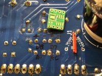
I opened up my TU-8200 today and checked the driver tubes heater voltage, it is indeed low at 5.8vdc. I’m going to replacing the BD107 with an LT4320 active bridge, that should pick up “free” voltage. If that is the case, I can keep R64 intact. If the voltage is too high, I’ll increase R64 to compensate.
The LT4320 pcb is very and will mount on the backside close to the red jumper.
Hmmm.... I referenced the LT4320 datasheet and 7vdc output is low for this device. This will truly be an exploratory surgery. I will continue, worst case, I must install another DB107.
The LT4320 pcb is very and will mount on the backside close to the red jumper.
Hmmm.... I referenced the LT4320 datasheet and 7vdc output is low for this device. This will truly be an exploratory surgery. I will continue, worst case, I must install another DB107.
Attachments
Last edited:
Hi Eugene,
Yes, they should, with the following comments.
C23,C24: I would use 15μF (same as C7 etc.) due to changes to some resistor values
C33,C34,C35: These are factory upgraded to 330μF already. You may want to try OS-CONs though.
Also check spacing between units before ordering bit caps. I hope it should be fine.
Ferenc
Thank you so much Ferenc. That is very helpful. Highly appreciated!
I have a few more questions regarding which capacitor to choose.
1. for C22 and C33, you give a range about capacitance to choose. For example, C22, 270-330µF, do you mean I can choose anything between 270 or 330? Which one is better, 270 or 330?
2. for C7,C8,C11,C12, I found Nichicon Series UCS, 15μF/400V at digikey.com, but max length is 22mm. You recommended Nichicon CS(M) 12.5x20 max length=20mm. I am not sure if these are OK.
3. for C13, C14, I found Panasonic SEPC OS-CON; ⌀=10mm, I think 10mm is the diameter right? You recommended ⌀=8mm, not sure if ⌀=10mm is OK.
I have spent quite some time trying to find the exact capacitors that you recommended. I think if the capacitance and voltage are right, and the size of the capacitor can fit in the space, that should be good enough, right?
I am comparing 8200r with Audioengine D1 that I have been using for headphone amp. I feel like the Audioengine D1 is slightly better in term of sound clarity. That's why I am trying to upgrade, hope to improve the sound quality. But I never hear the hum on headphone output as you mentioned. I am not sure if this will also improve the sound quality to drive speakers, I am pretty happy with the Tu-8200r driving speakers although I don't have other amp to compare.
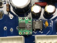
I couldn’t wait for the other part to be delivered so I worked on the D7 rectifier replacement. The DB107 was removed and replace with an LT4320 ideal bridge. I soldered up the few SMD parts required and used some resistor cutoffs as legs. It fits very neatly in the original DB107 location.
Voltage at the tubes was 5.8vdc, after the rectifier swap it is 7.7vdc! Almost 2 volts were gained. Yes, way too high now, I removed the R64 0R47 resistor and installed a pair of parallel 4R7 1W resistors. Now I’m at 6.5vdc, just about bang on. I’d say the first upgrade was successful.
I know this is probably over the top replacing a $0.40 part with a $10 bridge, but it’s the fun of DIYA!!
Attachments
(...)
1. for C22 and C33, you give a range about capacitance to choose. For example, C22, 270-330µF, do you mean I can choose anything between 270 or 330? Which one is better, 270 or 330?
The bigger is the better, but I could not find any Nichicon cap over 270μF/400V that would fit the space.
(...) max length is 22mm. You recommended Nichicon CS(M) 12.5x20 max length=20mm. I am not sure if these are OK.
When making my mods I carefully measured the max. length and diameter for each cap so if you exceed those you do that at your own risk. Why don't you open the case and do the measurements for yourself?
(...) You recommended ⌀=8mm, not sure if ⌀=10mm is OK.
See notes above. The diameter of the caps is printed on the PCB everywhere. You can probably use fatter OS-CONs if you do not push them fully into place, but that would look ugly.
(...) I think if the capacitance and voltage are right, and the size of the capacitor can fit in the space, that should be good enough, right?
Yes. Those that I recommended are premium models though.
(...) is slightly better in term of sound clarity. That's why I am trying to upgrade, hope to improve the sound quality.
These mods made my amp sound much clearer and more dynamic.
The bigger is the better, but I could not find any Nichicon cap over 270μF/400V that would fit the space.
When making my mods I carefully measured the max. length and diameter for each cap so if you exceed those you do that at your own risk. Why don't you open the case and do the measurements for yourself?
See notes above. The diameter of the caps is printed on the PCB everywhere. You can probably use fatter OS-CONs if you do not push them fully into place, but that would look ugly.
Yes. Those that I recommended are premium models though.
These mods made my amp sound much clearer and more dynamic.
Thank you so much. I have very limited knowledge of capacitor and electronic circuit, just start learning and I believe I have asked very novice questions. When I am looking for capacitors, there are so many different parameters that I am always afraid to choose the wrong one.
For example, for C13 and C14, I found Panasonic SEPG OS-CON; 470μF/16V ⌀=8mm. Everything matched with your suggestion except it's SEPG not SEPC that you suggested. I can't find the one match exactly as your suggested, The SEPC only has ⌀=10mm. I would assume if it's 470μF/16V it should be OK. Not sure if SEPC or SEPG will make a difference.
I have an old Sansui receiver that might need recap because it generate significant "hiss" background noise with both speakers and headphone, would like to take this opportunity to learn more. Thanks a lot.
- They also used standard values as much as possible, which is why you see many resistors and capacitors with the same values (180kOhms, 220μF/16V, 1μF/50V, etc.). This is perfectly fine, they do the job. The most extreme example is probably the bridge rectifiers. D5,D6,D7 are all the same even if they are used for very different purposes. D7 works the closest to its limits, and I suggest changing it to a 2A version even if you want to use 12AU7/ECC82 as the driver tube as the forward voltage drop will be a bit lower, which relates to the next topic.
Ferenc
Hi Ferenc, Thanks a lot for all you've been sharing.
A question if I may for the mod of D7, as I do not find the recommended DB207 but find SDB207.
I guess the key is that it's a 2A version as opposed to 1A the stock DB107. How about other parameters, in case?
SDB207 has 1,2V @ 2A Voltage Forward (Max) @ If
Whilst DB207 has 1,1V @ 2A.
Can I use the 1,2V version?
Thanks as usual.
I've made some of the mods per your sheet already, including replacing C22 with a 330 μF one. A dramatic difference already.
Kind regards
Sandor
Hi Ferenc, Thanks a lot for all you've been sharing.
A question if I may for the mod of D7, as I do not find the recommended DB207 but find SDB207. (...)
Hi Sandor,
SDB207 is the surface mount version of DB207. The 8200R uses DI1510, I would try to order its 2A equivalent DI2010. Also check size.
Ferenc
Hello SandorS,
I used the DF210-G as a substitute (D5, D6, D7) in my upgraded (per paczeltf) TU-8200DX
Peter
Thanks Peter!
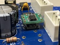
@paczeltf, I'd just like to say thanks for the thread. I just completed the list of modifications, or I almost did (I failed to properly heed the warning on C22 max length and a new one is on the way) I was only able to locate a surface mount for D7, but once that I saw only SMD were available I soldered some legs on the little fella and made it work. I can't really speak to the difference in sound, (it certainly doesn't sound any worse!) but I was swapping between the 6L6GC and EL34 and KT88 since I built it and hadn't had any issues as of yet, hopefully this will prevent any in the future.
I attached the spreadsheet that contains all the changes I made to the power supply and the bias circuit. Some of them like the slight increase to C33-C35 are not very important. I ordered parts that were easily available, you can use any other brand but check the size of the capacitors before ordering.
Ferenc[/QUOTE]
Hello Ferenc,
I finally completed the modifications you suggested using the parts from the attached spreadsheet and at the time of my previous post all was well when I gave the amp a brief soundcheck, though there were several components on backorder (I had substituted Nichicon caps for C31,C32, which I've since replaced with your recommendation), since my previous post and this one I seem to have developed a loud hum/squeal that is affected briefly by connecting ground wire to earth, but it starts right back up almost immediately. It happens with or without any input attached and isn't affected by the volume knob (it's possible that it is louder, or different coming from the right speaker, but it does come from both, though I haven't left it on for very long each time I have tried it.) I went over the main PCB checking all solder joints, but haven't proceeded any further. I was hoping that someone more knowledgeable than myself could give me some pointers on how better to diagnose my issue.
Re: desolder C5 and C6 cathode bypass caps
Hi Ferenc,
May I ask if I understand well that it's okay to simply desolder C5/C6, I.e. should not solder a wire instead the caps or do any further action?
I guess today the signal goes to earth which will change once I desolder C5/6. But I'm not sure.
Thanks a lot as always.
Btw, do you notice any sonic difference for Philips vs. Tungsram E80CC?
I use latter and find great overall, great transparency. Maybe a very little brightness at times, but will see after I desolder C5/6.
Sandor
Yes, the updates in my spreadsheet are recommended even if you do not want to make any other change to the amp except for tube rolling.
Almost 30 years ago I bought 4 Tungsram E80CC tubes based on Jean Hiraga's praising comments in l'Audiophile. These tubes had already been discontinued back then so that he recommended 12BH7A for the driver in his design as an acceptable compromise.
I wanted to design a build a tube amp but getting OPTs was very difficult back then especially here in Hungary, so that I designed and built a solid state amp instead. These 4 tubes, along with some Russian triodes that I stole from spare parts stock or simply pulled out of disassembled units during my military service, had remained in the closet for a few decades unused.
I thought I would give them try after the power supply upgrades and I was deeply impressed. I took 10 seconds to recognize the huge step forward via headphones, which resolved all my complaints about the overly warm and laid back character of the stock amp. The highs cleared up, the stage opened up into multiple layers, and the dynamics finally arrived. Mr. Hiraga was right...
Later, when playing music with higher volumes especially via speakers, I noticed some harshness in the treble. The reason is obvious. Even though the E80CC has similar bias current to the ECC82/12AU7 in the TU-8200, it has about 50% higher gain that affects both stages. This amp has a global negative feedback, and the resulting higher loop gain may cause transient intermodulation distortion and maybe parasitic oscillations.
The solution is simple - desolder C5 and C6 cathode bypass caps, at least if you like the sound otherwise. This will restore the loop gain and fix the harshness problem without sacrificing anything of the benefits of the tube replacement. No cap is the best cap anyway, so if you can live with a slightly less gain, you can get rid of C1 and C2 as well. In that case the negative feedback to the cathodes of the input tube needs to be restored by increasing R3 and R4 from 12 to 16-20 Ohms. (I use 20 Ohms and it works well.) The amount of the GNFB applied has significant impact on the sound, I even tried it without global feedback and it sounded flat and boring so "no feedback" is not always the best option as many believe...
Note that due to the higher heater current requirements of the driver tubes, you can use them with 6L6GC and its variants only. KT66 is on the edge but is probably OK. (I have a pair and have had no issues but preferred the RCA 6L6GC sonic character overall, not to mention the much neater look with this amp compared to the oversized KT66.) No EL34 or KT88 can be used as the total heater current may damage the power transformer.
All brands are great, right now I use Valvo/Philips variants mainly because I am not emotionally connected to them