[size=+1]Welcome to the high octane phono preamp![/size]
25-10-2015
Hannes Allmaier
25-10-2015
Hannes Allmaier
This site is intended to help in building this phono preamp. The circuit was originally published in Linear Audio #6:
http://linearaudio.net/article-detail/2159
and the dedicated forum thread you can find at
http://www.diyaudio.com/forums/analogue-source/242387-high-octane-phono-preamp.html
where everybody is heartily welcome to contribute!
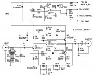
Schematics
The schematic of the high octane phono pre as published in LinearAudio:
It was also posted here:
http://www.diyaudio.com/forums/analogue-source/242387-high-octane-phono-preamp.html#post3631742
The boards
Please note that the boards given away are made 1:1 from my final prototype construction. Therefore, these also have a few warts, bugs and all, nothing serious but you will want to read the following building notes.
In terms of transistors, the usage of many low noise bipolar transistors is possible, although I of course recommend the use of the originally specified parts despite that these are hard to get. If you use different transistors, please check the pin-out and adjust the orientation of the transistor accordingly, if necessary.
The used 2SC2547 follows Emitter-Collector-Basis (ECB) pinout when viewed from its front.
Please note that the output CCS transistor Q4/Q104 is a rather special part, namely a depletion mode mosfet, which is normally on. From the electrical characteristics it is similar to common jfets but with much higher IDSS. Due to its special properties it is hard to replace and the usage of the original DN2540 is recommended. This part is in full production and can be obtained in the US from Mouser and Digikey.
If you have questions, just shoot me an email and I'll try to be of help.
I hope you will enjoy this little circuit as much as I do!
Happy building!
Please note
LinearAudio's Editor’s note: This document provides notes and information for building the High-Octane phono preamp as published in Linear Audio Vol 6 (Sept. 2013). The author also kindly provided the PCB Gerber files for personal and/or study use. Please contact the author if you plan to use this design or parts of it for a commercial purpose.
Building notes
The boards are identical to the one I used for my prototype (version v3e), which was improved during testing. So this version lacks a few small modifications to make it the final version 'f'. The schematic shown in the article is correct and considers all these modifications.
- Voltage regulator: do NOT insert CP1 (it will damage the opamp) and DO NOT ground its second leg (which is connected to the opamp input); the schematic shows correctly how CP1 should be connected (or leave it out simply)
- Amplifier inputs: leave out C6/C106 (C6/C106 is a remnant from the original circuit where it formed the cartridge load capacitance which is replaced by the switchable load capacitors in this version);
- Amplifier inputs: bridge R2/R102 with a jumper;
- Output resistors R5/R105 are not on the board but mounted on the output RCA’s.
The board has a few peculiarities you need to be aware of: the remote sensing of the regulator requires to connect VSENSE to SENSEV and GNDSENSE to SENSEGND with wires. PSU_IN and PSU_GND need to be connected to the external 48VDC power supply, and 1_IN/1_GND/1_OUT/1_OGND are the in- and outputs together with their grounds of channel 1 (replace 1 by 2 for channel 2).
Parts list
You can find the current BOM below; resistors are standard 0207 types (e.g. 0.25W) on a 10mm grid with the exception of RP1 in the power supply which is a 1W type 0309 (still 10mm grid). Part numbers for channel 2 are those for channel 1 + 100. The LED should have a forward voltage of about 1.6 V.
These are the parts I used for the preamp. In some cases I added the parts numbers from Farnell/Mouser in case you have access to this distributor. Of course the same or equivalent parts are available from Digikey and Mouser.
Please note that the RIAA resistors and caps need to be mounted partly from the bottom and the RIAA polystyrene caps need to be mounted standing upright due to the limited space available. Isolate the bend leads of the RIAA-caps to avoid shorts. Just look at the photo of my prototype in the article and you'll see what I mean.