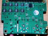
Nope, right on the board and it looks like the clock signal is input to the VHC574 that I suspect is used for distributing the I2S signals to the DAC chips.
My apologies, you're talking about the 'Hat' DAC for RPi, not the original topic of this Wiki.
My apologies, you're talking about the 'Hat' DAC for RPi, not the original topic of this Wiki.
That's funny... when you posted the link to the one on Taobao that is similar to this one AND also an R-Pi HAT DAC, I thought you realized that then. Funny, that's all that jonners' & bommetje's posts have referenced.
Interesting that the one that started this Wiki thread DOES have 8 TDA1387s, but does not have a clock used as part of the I2S distribution? The DAC HAT one from Taobao DOES appear to have a clock just like the Audiophonics board AND that area of the board also looks like it would accomodate the TCXO used by Audiophonics.
Oh well, any thoughts?
Greg in Mississippi
P.S. Jonners & bommetje, how are you powering your Pi & your Audiophonics cards?
I power the hat from pi to hat with ifi power. Somehow powering them separately, or from hat to pi does not work. Still have to look into that, maybe something wrong in the audiophonics dac 5V circuit? The TDA1387 hat also works with Allo Kali, which surprised me because of the ' mysterious' clock, was expecting a master slave issue. But I am not very experienced. I just got interested in diy audio. ( I did remove the 5V jumper when trying to power them separately.)
Last edited:
P.S. Jonners & bommetje, how are you powering your Pi & your Audiophonics cards?
Powering Pi and DAC via Kali with iFi Power.
That's funny... when you posted the link to the one on Taobao that is similar to this one AND also an R-Pi HAT DAC, I thought you realized that then. Funny, that's all that jonners' & bommetje's posts have referenced.
I realized that those other posts were about the RPi DAC, dunno why I just assumed your post had reverted to the original topic. I often have problems working out what context people are coming from....

Interesting that the one that started this Wiki thread DOES have 8 TDA1387s, but does not have a clock used as part of the I2S distribution?
Right, no need for a clock distributor. I've built a DAC that had (I think, memory isn't what it used to be
) 19 TDA1387s in it and I didn't use any clock distribution IC, just paralleled all the BCK pins. So its definitely not a requirement on a drive ability basis.Oh well, any thoughts?
Having played with multiple DACs in parallel, I'm left wondering whether there's any technical reason for putting 8 in parallel beyond getting a lower output impedance. Which in itself is a decent technical objective, however active I/V achieves it more elegantly.
Abraxalito,
Thanks for the info. At some point I'll trace what they are doing with the 50mHz clock signal, but that''s low on my priority. As I said, if it looks like they are using it to gate the timing of the I2S signals (which sounds like a really dumb idea to me), I may try doing the same with the clock signal from the Kali instead of the on-board clock.
Maybe that, some really good power, and some improvements around the I/V will make it sound decent.
But in the meantime I have other projects to burn.
Jonners & bommetje, thanks for the info on the power. When I try it I'll figure out how to power it separately... I've always found separate supplies for the Pi, the Kali, and the DAC make a significant improvement... and even separate supplies for the analog and digital sides of the DAC chip if it can be powered that way, like the PCM5122 (and the PCM1793, which is one of my next DAC HAT projects).
Later!
Greg in Mississippi
Hi, I just got the hi-hat 8 x tda1387 dac for Pi. Burning in right now, its a smooth sounding dac with decent bass. I am powering it with a portable phone battery with 2.4A current out.
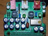
This dac uses passive I/V out with caps and inductor for filter and Muses BP 10uf for coupling. My version has a 50mhz TCXO 0.1ppm crystal .
This dac uses passive I/V out with caps and inductor for filter and Muses BP 10uf for coupling. My version has a 50mhz TCXO 0.1ppm crystal .
I worked out the signal out from tda1387. The inductor is use for filtering high fz noise from dac output. I suspect the passive out filter can be further optimized. I have a cheap portable scope, but I don't have the knowledge to measure the output.
TDA1387
=> I/V resistor 500 ohm
=> RC to ground 33R +3.9nf (square blue cap on board)
=> Inductor (marking 103)
=> RC to ground 2.7k + 0.22uf (round blue cap, but resistor label 2.2k)
=> Nichicon BP 10uf for coupling
=> smd cap (label 47k) piggy back with COG type at bottom (my guess as the cap looks lighter)
===> RCA out
Attachments
Last edited:
Hello. Nice thread. Me and a friend, have the portable version of this DAC. Very impressive little thing, compared to much more expensive equipment. Kind of surprised me how bright it is, for a multi-bit. We would like to remove some of that treble harshness as in the second mod on the list, but the pcb layout is quite different.
Is it as easy as removing the blue 2n2 in the top?
The portable version has a small smd tda opamp, which I was thinking about replacing with a dip8 socket. Will also be replacing all thru hole capacitors for better spec ones.
Other mod recomandations is much obliged.
-Morten
An externally hosted image should be here but it was not working when we last tested it.
An externally hosted image should be here but it was not working when we last tested it.
Is it as easy as removing the blue 2n2 in the top?
The portable version has a small smd tda opamp, which I was thinking about replacing with a dip8 socket. Will also be replacing all thru hole capacitors for better spec ones.
Other mod recomandations is much obliged.
-Morten
As far as I can work out this board is using passive I/V (the 560 ohm resistors look to be the best bet for doing that function). Whereas the mod to the original DAC deletes the 2n2s in the feedback loop around the output I/V opamp. Meaning that if you've got harshness you're not likely to tame it by removing the 2n2s.
560 ohm is too big a value for I/V - given the full-scale current (assuming 5V supply) is 8mA then the swing (peak to peak) of the output signal is going to be 4.5V which exceeds the compliance range of the DACs. Seeing as this looks to be USB powered 5V is a reasonable guess which means lowering those 560ohms to 430ohm.
The harshness in HF you're experiencing could easily be the result of having no isolation on the USB. Worth putting a USB isolator in between this DAC and your computer. You can get them cheaply on Taobao nowadays - for example https://item.taobao.com/item.htm?sp...7w1do&id=522874428774&ns=1&abbucket=12#detail
This one IS purely usb powered. I am powering mine with an iFi nano iUSB, so it is completely isolated.
I find it brighter than expected. I do not know if this is comparable with the harshness you guys are experiencing.
Why would Lee choose 560 ohms in the first place, and what will changing this value achieve? Is it the 2 resistors with 620 marked on pcb we are talking about?
I find it brighter than expected. I do not know if this is comparable with the harshness you guys are experiencing.
Why would Lee choose 560 ohms in the first place, and what will changing this value achieve? Is it the 2 resistors with 620 marked on pcb we are talking about?
I can only guess why 560ohms chosen - perhaps the designer didn't read the DS carefully. Or perhaps it really does not clip at 4.5V output because the DS is too pessimistic? Its common to see DACs with the wrong values for I/V resistor - I seem to recall my Lite DAC-AH needed the values changing (reducing).
With the 560ohms you run into the likelihood of clipping at the highest levels of output. Yes they're the values where 620 is shown on the silkscreen.
With the 560ohms you run into the likelihood of clipping at the highest levels of output. Yes they're the values where 620 is shown on the silkscreen.
I'd advise getting rid of passive I/V but such a mod isn't a simple matter, at the very least you'd need a handful of discrete transistors and a voltage reference. I'd then suggest a passive (LC) filter - partly to remove images as the DAC's NOS, and partly to EQ out the NOS droop.
The simplest mod though is to add at least 2200uF to pin7 (between pin7 and pin4) which gives a more clearly delineated bass.
The simplest mod though is to add at least 2200uF to pin7 (between pin7 and pin4) which gives a more clearly delineated bass.
Yeah, I must admit I had to read up on passive and active I/V. ( SW1X Audio Design Passive vs Active I/V conversion ) I'm not completely sure I'm capable of doing that, without a very detailed schematic. Or some guide on here, doing it similar.
Soldering capacitors on this DAC is quite doable. It has to be chip side of PCB, though. Does it have to be 2200uf? #1 in this thread says 1000uF.
Will still be desoldering the smd opamp and adding a dip8 socket. Should there be anything wrong in using OPA2132? I like the sound of that opamp in small A47 amps.
I posted up a schematic for one simple method of active I/V in the thread linked in post #1. No the capacitance doesn't have to be anything, just more is better. If you love the sound of a particular opamp then by all means go for it. A quick look at the DS for OPA2132 shows its going to be jolly marginal when powered from a USB socket - its min supply is 5V and at this voltage the output swing is just 2V (unspecified load).
Dear abraxalito and matt_garman,
Thank you both !
Today I hooked up the TDA1387 x8. Have already replaced the NE5534 op-amps with AD845. That change alone took away a harshness and increased the musicality. Next will remove the 2n2 op-amp feedback capacitors. I am glad have tried the TDA1387 x8, it is not the most revealing Dac or the most spacious, but it is musical. The output sounds like music not "bits".
Have you tried Ian's I2S FIFO KIT with the TDA1387 x8 ?
I am using:
Internet Radio > Macbook Pro > TDA1387 x8 > JLH1969 Headphone Amp
I welcome any suggestions or comments,
Thank you !
- Status
- This old topic is closed. If you want to reopen this topic, contact a moderator using the "Report Post" button.
- Home
- diyaudio.com Wiki
- TDA1387 X8 NOS DAC