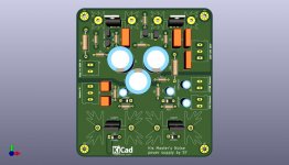
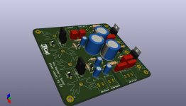
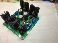
Power supply for one channel. KiCad and gerber files attached.
Enjoy !
Regards,
Tibi
For the regulated HV -- it's good to cut a slot between these traces at the output, or keep the separation distance between traces "large".
You've shown a ground plane for the heater supplies -- important to note that this is elevated above ground by 30V.
Thank you for observations, Jackinnj !
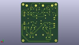
Clearance between 260V and 160V is over 1mm, so this will be enough.
HV ground is completely isolated on pcb top and clearance at each hole is 1.5mm.
Heaters ground plane is lifted by resistor divider and between HV GND and Heaters GND is a large clearance of over 2.5mm.
All files have been already attached, anyone with little effort may change the design as he/she consider.
Regards,
Tibi
PS. I have ordered few boards and will post here pictures when finished.")
Clearance between 260V and 160V is over 1mm, so this will be enough.
HV ground is completely isolated on pcb top and clearance at each hole is 1.5mm.
Heaters ground plane is lifted by resistor divider and between HV GND and Heaters GND is a large clearance of over 2.5mm.
All files have been already attached, anyone with little effort may change the design as he/she consider.
Regards,
Tibi
PS. I have ordered few boards and will post here pictures when finished.
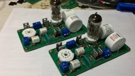
PCB's
Hi there!
I still have a couple of D3A's that I have never used except once to test a driver stage and the tubes have sadly not been used since.
I came accross them again yesterday when I was going trough all the stuff on my bench and thought why not put them to good use in a phono pre like I once planned to do and His Master's Noise came to mind.
Has anyone got the needed (unpopulated) PCB's and would be willing to sell them?
Oh, and has anyone built this pre with D3A's not only as V1 and V2, but also with a D3a for the cathode follower and would like to share whether it was an improvement or not and if yes, how it affected the sound /if it was worth it, or if it is really more for show than for anything else, like mentioned in the first post?
Thanks,
Brzzl
I think most DIYers would be happy to own a D3A at all. I don't think anyone in this thread has ever tried it.
If you are seriously considering this, the red LED will have almost no anode current at 90V anode voltage. Then you would have to replace it with another IR-Led. At 10mA the nonlinear range of the D3A starts. So you should set the CSS a bit higher.
If you pay attention to this it should be no problem to use the D3A instead of an E88CC.
However, it will hardly bring you any sonic advantages. Except a higher gain.
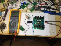
I am nearing the end of building HMNP. but i've got a real problem I can't figure out.
I've built each of the voltage regs more than once they check out at 258 & 159. And have set the ccs's at 20 ma and 10 ma per sys's design. when I bring up the voltage it seems ok but then slow the voltage at the output of one of the channels goes on run-away, after a few minutes at 2-3mv it starts to climb goes above 1 v and then really takes off to B+ 305v and that when i've shut it down. The first time i did the smoke test it blew up and i've had to rebuild the voltage regs. Whats the problem? is it a bad transformer bleeding into the ground line? I've checked and replaced all the caps. Each of the current sources tests OK at low voltage and the current is set pretty simply. It only happens in one channel?
I've built each of the voltage regs more than once they check out at 258 & 159. And have set the ccs's at 20 ma and 10 ma per sys's design. when I bring up the voltage it seems ok but then slow the voltage at the output of one of the channels goes on run-away, after a few minutes at 2-3mv it starts to climb goes above 1 v and then really takes off to B+ 305v and that when i've shut it down. The first time i did the smoke test it blew up and i've had to rebuild the voltage regs. Whats the problem? is it a bad transformer bleeding into the ground line? I've checked and replaced all the caps. Each of the current sources tests OK at low voltage and the current is set pretty simply. It only happens in one channel?
I am nearing the end of building HMNP. but i've got a real problem I can't figure out.
I've built each of the voltage regs more than once they check out at 258 & 159. And have set the ccs's at 20 ma and 10 ma per sys's design. when I bring up the voltage it seems ok but then slow the voltage at the output of one of the channels goes on run-away, after a few minutes at 2-3mv it starts to climb goes above 1 v and then really takes off to B+ 305v and that when i've shut it down. The first time i did the smoke test it blew up and i've had to rebuild the voltage regs. Whats the problem? is it a bad transformer bleeding into the ground line? I've checked and replaced all the caps. Each of the current sources tests OK at low voltage and the current is set pretty simply. It only happens in one channel?
Did you heat sink the pass transistors? They will burn quite a few watts if the raw B+ is much over +300VDC. If you're raw DC is high, consider using a power resistor to dissipate some of the excess energy.
R23 and R26 -- don't skimp here -- 1 Watt resistors please.
We can buy the pcb ?Time to heat the iron !
Regards,
Tibi
Order your pcb at desired manufacturer. I have posted source files
here:
His Master's Noise: A Thoroughly Modern Tube Phono Preamp
and power supply here
His Master's Noise: A Thoroughly Modern Tube Phono Preamp
Gerber files are needed ones.
Regards,
Tibi
here:
His Master's Noise: A Thoroughly Modern Tube Phono Preamp
and power supply here
His Master's Noise: A Thoroughly Modern Tube Phono Preamp
Gerber files are needed ones.
Regards,
Tibi
Order your pcb at desired manufacturer. I have posted source files
here:
His Master's Noise: A Thoroughly Modern Tube Phono Preamp
and power supply here
His Master's Noise: A Thoroughly Modern Tube Phono Preamp
Gerber files are needed ones.
Regards,
Tibi
thanks for your prompt reply.
Anyone want to order both pcb ??
Last edited:
I have buildt the amplifier section with jackinnj’s boards, and the regulators with tibi’s boards.
The low high voltage is spot on but the 260v is locked at 212 V ...
So i need to change some resistor values to up it. I am not used to these sandy things, so
A few inputs about how the reg works and which values to change would be very nice
The low high voltage is spot on but the 260v is locked at 212 V ...
So i need to change some resistor values to up it. I am not used to these sandy things, so
A few inputs about how the reg works and which values to change would be very nice
- Home
- General Interest
- diyAudio.com Articles
- His Master's Noise: A Thoroughly Modern Tube Phono Preamp