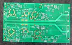
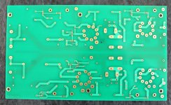
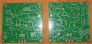
Yes, the Equal Opportunity. I am making my own PCB and working with SY to get the latest updates. As for the unbalanced output, I am thinking of using a JT-10K61-1M and omitting the output buffers.
I didn't do PCB's for the EO -- if you want a balanced JFET front end, then build a balanced JFET front end. The grounded grid amplifier with JFET input is a solution in search of a problem.
Cause much people are interested in this project, i will post some hints for a faster building of the amp.
- the load resistor R1 is 6,8K. It had to be calculated carefully. The sound of my set up was awful. I changed to 56k and the sound changed to clear and marvelous.
- if using the D3a, use for R7 18,7k (1% tolerance) and 34nf (if possible 1% tolerance). Use for R8 2,61k. So you match the RiAA-line near perfect. You have a difference of 0,5dB at 20kHz.
- the current defining resistors with 120 and 300 Ohm are to large. I builded in the meanwhile 5 Boards for friends and me. I used for my DN2540 (in Europe bought) this solution:
Use for the first stage R5 between 68 and 82 Ohm. That gives me 20mA. In most times 82 Ohm matches 20mA.
For the second stage R14 and the cathode follower R18 use 150 to 180 Ohm.
- for a cheaper building you can use the T092 Version of DN2540 (G3) for Q1, Q3, Q5 and Q6.
- Sy used a red led for biasing the second stage. I found no red led with a correlating forward voltage. I used yellow leds. But a higher bias is no problem. The bias point is a little suspended.
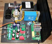
Ha, that looks so different to mine! I think Im probably going to replace my transformers with some torroidys, (i know it says not to use torroidal, but they seem to be the best transformers Ive used and they dont hum). Im really not happy with the one i got made. You found some r cores by the looks of things, Where did you get those?
Funny you should mention R1, I spent a couple of days trying out different value with the scope for this. I have the posh sowters (not the ones Sy had) and supposedly they should use just a 47k. I did try that on the bench but settled on something else with a zobel network. I think it did limit the bandwidth a bit but got rid of ringing and kept the gain whilst keeping pretty square square waves. I should try the 47k in situ just to see.
Cheers
D.
From the first time I read this topic, the value of R1 = 6k8 seemed strange to me.
Due to the gain of the Sowter 8055X (1:10), we have an impedance transformation of 100 (10 squared). With R1 = 6K8 the cartridge "sees" only 68 ohms. Typically, 10 times of cartridge impedance is the starting point - or 150 ohms in the case of the Denon 103R.
My cartridge is a Denon 301-mkII so 68 ohms is 2x its DC resistance ... very low and probably will sound somewhat dull
Anyway I'm planning to use a pair of Lundahl LL9226 instead of Sowter so I have to calculate / test R1. 6k8 would not work for me anyway
Last edited:
If somebody wants a R-Core-Transformer; absolutely no noise:
2016 LITE R-80 Type 100VA R-core Transformer --A variety of model is optional | eBay
2016 LITE R-80 Type 100VA R-core Transformer --A variety of model is optional | eBay
Hi jpjindex, i think you are right. Tell us your experience, when you are ready.
Sure Frank... I'll do that.
Which cartridge and input transformer do you use?
Are you building the circuit on breadboard and measuring the current for that specific device or using the listed value. There can be be quite some variance between devices.
Is your multimeter within reasonable calibration? From what I remember you can run some of these tubes over a fairly wide range so a few milliamps out should still be OK, your problems suggests they're very out.
Are you also being careful of static? Don't build on plastic veneers! I learnt this the hard way with synthesiser circuits. Caused all sorts of problems. If you don't have an esd mat then put a wooden or mdf board down.
If you think all that's OK. Stick a heat sink on anyway.
Is the d3a 20mA? Of the 3 tubes I've used this cca on one was significantly hotter than the rest. I think the 6sn7 (impasse) was 8ma and I still put heat sinks on that.
Again a currrent source of the D3a died...overheating I suspect...
DN2540?
I killed a dozen of them (inrush spikes? fake batches from Mouser?) at using only over 300V.
Now I use IXTP01N100D everywhere (as "upper" FET of cascode CCS).
Hmm that's interesting. I got mine from mouser but not had any problem. The hmn shoves a max of 260v into the cca for the d3a and I think the impasse has about (iirc) 350v but then drops a load across a resistor so I've not been taxing them like you have. Having said that, does the input voltage matter that much? Isn't it. The drop across them that's the issue. The reason I say this is the way voltage regulators work, they can be used at very high potential as long as the drop wasn't more than 30v or so?
DN2540?
(inrush spikes? fake batches from Mouser?)
I've been dealing with Mouser for over a quarter century and never got a fake component from them.
Are you building the circuit on breadboard and measuring the current for that specific device or using the listed value. There can be be quite some variance between devices.
Is your multimeter within reasonable calibration? From what I remember you can run some of these tubes over a fairly wide range so a few milliamps out should still be OK, your problems suggests they're very out.
Are you also being careful of static? Don't build on plastic veneers! I learnt this the hard way with synthesiser circuits. Caused all sorts of problems. If you don't have an esd mat then put a wooden or mdf board down.
If you think all that's OK. Stick a heat sink on anyway.
Is the d3a 20mA? Of the 3 tubes I've used this cca on one was significantly hotter than the rest. I think the 6sn7 (impasse) was 8ma and I still put heat sinks on that.
Electronic eng, basics are in place and the D3a is indeed 20mA
- Home
- General Interest
- diyAudio.com Articles
- His Master's Noise: A Thoroughly Modern Tube Phono Preamp


