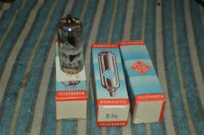
I got 4 on Ebay from a seller in Germany, $100. He wanted more but I gave him a best offer of $100 and he took it. Arrived in fine condition.
That sounds like a good deal, not like $100 for just one tube from the Tube Depot website.
Good morning everyone,
After going through my boxes of parts I found a nice toroidal transformer that will work nicely for this build. It's an audio grade toroidal manufactured by Toroidy in Poland with two secondaries at 250V / 200mA with secondaries for the heater supplies as well. The current is twice as needed by the photo preamp, but I already have it so I'll use it.
This transformer has two secondaries at 250V each and no markings to indicate which wires are in phase with each other. Not sure if this is the right terminology but I hope you're following.
If my electronics brain cells are working well, I can connect the two in series and use it as a 500V with a center tap. The question is, how do I find out which wires to connect without an oscilloscope where I could see the phase of each secondary? Do I do it by trial and error?
Lets say I have secondary A with wires A1 and A2 and secondary B with wires B1 and B2.
If I connect A2 with B1 and measure the voltage across A1 and B2 and my DMM tells me I have 500V I'm good? Otherwise try connecting A2 to B2 and measure across A1 and B1?
If my train of thought is right, If I connect the secondaries in series at opposite phase I would get 0V. Correct? Any risk of damaging the transformer while doing this?
I also found some nice caps for the output of the HV regulators. These are 100uF + 100F @ 500V. I have two, which would be OK if I can upgrade from 47uF to 100uF and use the two capacitors in each can for each HV regulator.
Each can would be used for each channel and one of the capacitors inside the can would be used for the 160V regulator and the other for the 260V regulator.
Each can has three pins, a common ground and two for the positive. Would this be OK?
The caps are like the one on the top left: https://hfc-fs.s3-eu-west-1.amazonaws.com/s3fs-public/mundorf-hv-new-range-all-800.jpg
Although mine are just 100 + 100.
Last question, which caps should I use for the RIAA network? Some sources recommend MKP (metallized polypropylene) while others recommend polystyrene. Some options are Vishay Roderstein MKP-1837, Wima MKP10, Wima FKP2. Allen Wright used to recommed FKP2 which are available in 1% tolerance.
Capacitor C1 in the RIAA network is 0.1uF and is not availabe in the FKP2 1% series. What would be the alternative?
Still regarding the RIAA network, would it make sense to mount the components on a separate little board that could be tested and trimmed with a signal generator and an oscilloscope and then connected between the two stages? Recause R7 (20K + trim) is calculated to take into account the output impedance of the D3a tube, an additional resistor would be needed to compensate for that. Would this be a good approach or do I need to trim R7 and C2 once both channels are working?
Cheers,
Luis
Right, I'll see if I can help.
The torroidy tx is fine for the raw ht, plenty in reserve so it won't sag. If it has an electrostatic shield connect to chassis with shortest amount of wire. I don't think the audio grade does though.
Heaters, I don't think you can use the heater of torroidy. That would most likely have a single 6.3v supply, this can be used for ac heater supplies. You could rectify this and regulate but you would probably find that there's not enough headroom for the regulator for a 6.3v supply but you might get a 5v dc heater supply. This doesn't help us here though.
As far as I know there are 2 reasons for elevating the heater supply. This is super imposing dc onto the heater supply to raise it 60v or so. 1 is to reduce hum and the other is to avoid pushing the tube out of spec. I can't remember the actual parameters but something like heater to cathode voltage.
Anyway, regardless, whether you have an ac heater or a dc heater you need a center tap supply for the heater to do this. So you can either use a 6.3v with a centre tap, stick 70v or whatever on the centre tap and drive ac heaters like the impasse circuit.
Or in the case of hmn, use a bigger dual winding tx, then 1 or 2 sets of rectifiers and 2 regs, giving one channel of the circuit maybe 63v to 70v and the other channel 70v to 77v.
If we tried to do this using a single centre tap winding we and one reg I think we would run into problems with both tying the output to something steady and increased current demands on the regulator itself.
This project uses a dual 10v tx for the heater (2x 9v is fine), 1 bridge rectifier and 2 regs, this halves the current demands of the each reg and ties the output to something rather than leaving them floating.
With regards to using dual caps for different parts of the circuit, yes, it will most likely work but I think you will suffer decreased performance. Usually when putting circuits together it's a good idea to try and get the ground of that functional block of the circuit as tight on its self as possible. Using your dual cap you would either have to be very clever in your layout or you would end up with a couple of long wires going from one reg off to where the cap is placed. This seems like a really bad idea to me.
I think I used mkp, I think ones that stay stable over time are probably best.
I would buy about 10 of each and then match the values on a bread board so you know your capacitance is matched channel to channel, solder into pcb then trim the resistors on the pcb using a signal gen and scope. I did this just for the riaa circuit and the board wasnt powered. Its my understanding that channel matching is more important than following the riaa curve precisely. (let's face it, most speaker systems deviate fairly widely).
Do you have a scope? I seem to be getting conflicting info here. You need one to do the riaa.
If it's dual channel you can use this to sort out the leads on your torroidy. Use a 10v signal generator and measure the outputs on your scope and see what they do. You can play about safely here without risk to you or your tx.
Hi Dave,
Thank you for your reply!
My transformer has two 250V 200ma secondaries and two 12V 1.5A secondaries.
That way I can make the 500V with CT and 24V with CT. The voltage for the heaters is a bit higer than necessary and that will mean more heat in the LM317/337 regulators. I'll use larger heat sinks and that should take care of that.
I don't own a scope yet, I'll borrow one eventually once the thing is working. If the preamp is working, without smoke and I get audio at the output, then I'll borrow a scope and trim the RIAA.
If I mount both 160V and 260V regulators for each channel on the same board I can get the two outputs close to each other and I can place the dual cap there. It will be two inches away at most.
With a good layout I think it may work well.
--
Luis
The layout I did for the ht regs was 2x160v on one board and 2x260v on the other. These then line up down the middle between the output boards quite nicely.
I would be tempted to use your dual caps so both sides work on 160v L + R and the other on 260v L + R. I think you'll find the overall layout of the boards in the case a bit easier.
If you intending on using a 2 box solution with a cord a couple of things:
1. Make sure the raw supply has the female side of the connectors so you're not waving live pins about.
2. The raw supply takes about 5 minutes or so to discharge when the phono stage is disconnected. Make sure the raw supply has discharged before reconnecting. I blew up one pair of regs because I didn't do this.
Last question, which caps should I use for the RIAA network? Some sources recommend MKP (metallized polypropylene) while others recommend polystyrene. Some options are Vishay Roderstein MKP-1837, Wima MKP10, Wima FKP2. Allen Wright used to recommed FKP2 which are available in 1% tolerance.
Capacitor C1 in the RIAA network is 0.1uF and is not availabe in the FKP2 1% series. What would be the alternative?
Hi Luis,
I built SY's Equal Opportunity MM phono pre amp which is a moving magnet variation on the His Master's Noise. Since SY designed both, the RIAA is almost identical and I did a bit of playing with the RIAA caps, so I thought I would throw you some alternatives.
First comment is you better get cap sizing information on the board before buying any caps. The board that mrdave45 has is different and may have more room than the boards I built, but I found cap spacing tight.
I see the 34 nF* in the schematic and assume it is a 33 nF || 1 nF as in my build.
In the Wima world, I preferred the FKP2 compared to the MKP10 and also the MKP-1837. On other projects, I would take an FKP4 or MKP4 over the MKP10 also.
I usually like polystyrene caps, but they are hard to find in bigger sizes. I tried an axial 33 nF and it sounded very clean, but ended up very slightly preferring an old Siemens cap which is not available any more. For the 1 nF, I ended up using an Amtrans AMCH because I already had it. It's a nice polypropylene film foil cap, but I didn't see much difference between caps here.
If you are looking for something a little different, I used Amtrans AMCO caps for the 0.1 uF positions. I usually wouldn't recommend a metallized PET cap, but Amtrans does a nice job. It sounds very neutral with a little more high frequency clarity than the Wima MKP4. Of course, it might not be the right choice if your system is on the bright side.
The Amtrans and polystyrene caps are available at hificollective and are not too expensive. They might also be willing to match cap pairs if you ask. Of course, the Wima's are widely available. I hope this helped. Good luck with your project.
Jac
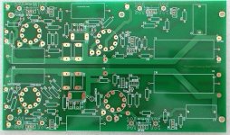
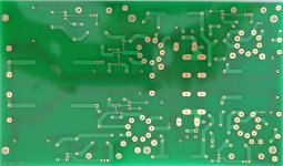
Boards are $3.00 shipping to Portugal probably $9 or $12. It depends on which clerk at the post office
Hi Jack,
Great to hear from you!
Are the boards just for the audio circuit?
Do you have a photo of the boards?
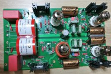
And maybe assembled board?
How did the tests turn out?
Cheers,
Luis
It depends on which clerk at the post office
So true.
Hi Jack,
Great to hear from you!
Are the boards just for the audio circuit?
Do you have a photo of the boards?
And maybe assembled board?
How did the tests turn out?
Cheers,
Luis
See this post, and those surrounding: His Master's Noise: A Thoroughly Modern Tube Phono Preamp
Hi Luis,
to trim the RiAA you have to use the complete first stage, cause the Resistor (i think Ri) is part of the RIAA network. Read Sy´s explanation carefully. Its very helpful.
Myself i used measured and matched 10nf Mica East-Europe. My RIAA-network matched with 3 x 10nf Mica, 3,3 nf Wima FKP2 and 680 pf and 20,7K as R7.
If you are interested at the Mica, mail me, please.
Myself i used measured and matched 10nf Mica East-Europe. My RIAA-network matched with 3 x 10nf Mica, 3,3 nf Wima FKP2 and 680 pf and 20,7K as R7.
Mica caps are great, I find them very neutral. Did you do your own board? It looks like the board was made with the 3 parallel Mica + FKP2 designed into the board.
I love that you have space for the big axial caps too.
Jac
Hi Jac,
the Micas are great. I made this board first for mounting in my Hovland HP100. As I developed the board, i made sure that there is place for different capacitors and for the Micas I owned. The best is, the most russian or east-european Micas have a tolerance from 0,5 to max 1 percent. Now is the hovland sold and i have to build a case for the noise-machine.
I build a second board (this is sold) so i bought 100pcs 10nf Micas (matched). Fortunately they match the place on the board.
If somebody is interested in Micas, please ask.
I would be tempted to use your dual caps so both sides work on 160v L + R and the other on 260v L + R. I think you'll find the overall layout of the boards in the case a bit easier.
Hi Dave,
Thank you for your tips!
I'll have to work on the layout of my build, but I guess it will be close to yours.
I'm planning on one box only, so there will be no cables with HV plugs.
--
Luis
Boards are $3.00 shipping to Portugal probably $9 or $12. It depends on which clerk at the post office
Hi Jack,
Thank you for your reply. for now I think I'll work on a point to point construction of the signal circuit, with the CCS on small breadboard style PCBs. It will give a bit more freedom in the layout.
I'm very keen on tube amps where the tubes pop out of the box and you can see the tubes glowing. I understand it is a very romantic idea, but I guess that is why we spin vinyl on our turntables to start with.
--
Luis
- Home
- General Interest
- diyAudio.com Articles
- His Master's Noise: A Thoroughly Modern Tube Phono Preamp


