VizualXTC said:Thanks again for your fast reply.
I was actually thinking at first about doing the auto HID mod, but then I saw these LED's. From what I understand the HID bulbs for automotive applications run about the same amount of hours (~2000 - 3000) IIRC. I love the idea of doing this once and not having to worry about it again. I know the HID bulbs are only like $35-45USD so it's cheaper, but then I have to mod it every time the bulb goes out.
In response to the problems you suggested:
1: The driver for the LED that I posted says it takes a voltage of ~85-265V and drops it to the 30-36V required to drive the LED. I may be reading this wrong, but that's why I was thinking the driver would work.
You cannot use this power supply. The power supply wil ONLY work with an hid lamp. The starting voltage ranges from 1000-2000 volts and it is current regulated. You will have to get a special power supply for the LED or something is gonna fry or explode.
2: I don't know exactly what you mean by the focal length of the lens. Does this mean the distance it takes to focus the light to the claimed point?
Yes
3: For the heat issue, I was going to use a heat sink, and the stock fan to cool the LED. I can't imagine the LED displacing more heat than the stock bulb, although, again I might be wrong.
100W is going to be the heat output. This is almost 2 times hotter than a PC processor. You will need a large heatsink good thermal paste and a fan on the heatsink. Think of a 100W lightbulb runing for some time and grabbing it. Thats how hot ur led will get. Hot enough to burn you badly and hot enough to burn up with bad cooling.
4: The color wheel will divide it by 2.4 meaning the LED's 7000LM would only put ~2900lm to the projector lens. Is this what you mean? (Sorry, I have to ask because I don't want to assume anything and make a wrong decision.) If this is correct, that will provide almost 2000lm more light to the lens than the current bulb provides because the 4805/HD102 is rated at 800lm. I'm sure extra light will be lost through the various lenses used in the DLP process.
Projector lumen ratings are never correct that projector prob gave 500 or less to the screen and 8000-10000 from the lamp
Would this give me a better contrast ratio if I have a brighter picture?
Only with the color wheel removed do you increase the contrast ratio. True black can be achieved.
5: Optics meaning placing the LED's center/focal point 1mm off in any direction?
With the tiny light tunnel in the DLP 1degree of angle can ruin the brightness.
If I could find a high output (1000lm+) RGB LED I would try your other suggestion. I could maybe make an array of high power 10mm RGB's (found some with 360K mcd) and use that, but I'm afraid it won't have the light output required. I know how to program, so programming the micro-controller would be the easy part. The hard part would be finding the frequency of the color wheel, and building a board to accept the PWM and drive the LED. I know little about circuitry, but I'm always willing to learn.
Multi Led arrays are not that good. You cant focus all the led's to one point. You will need an LED like this. http://www.luminus.com/content1467
You may be able to remove the prism thing from am LCD projector and use that with 3 led's. This is something i never researched but in theory with RGB led's it will pass the light. It will mostly be trial and error and your still better off with HID. It takes 30 minutes to replace the lamp and plaster it in place.
Thanks again for your help.
I appreciate all your help. I will do some trial and error runs and see what works. First of all, I will take your advice and try the HID light first. There is only one question I have. In my original post I thought you did the bypass of the ballast to remove the ignition sequence so that it didn't give the high voltage initially, and just puts out the 'lamp running' voltage. Is this what you have done?
I will let you know now, that I am a very persistent and will keep trying to get the LED to work, and if by the miracle of GOD it works, I will post my results on here for others. I will more than likely do a work thru on instructibles.com. Thanks again for all your help, and if you have any other ideas or concerns that we haven't covered, I would appreciate if you could inform me of those as well.
I appreciate everything man.
~Ryan
The ballast doesnt even function without the lamp enable lead connected. The Auto 35w HID is powered from a 12v supply and its own ballast. Both outside of the projector.
****UPDATE****
Just for the hell of it I removed the optics cover and put a 900 lumen sscp7 LED shining on the lens before the DLP The image is dim but extreme contrast and clarity in greyscale. Shining through the color wheel I cant even see the image on my screen so I guess since I have 2x2's im gonna hack this one and see what happens.
Well I am going to try to get my hands on one of these for some testing.
http://www.luminus.com/content1513
Then its off to do some homework and play with PWM to drive this thing.
http://www.luminus.com/content1513
Then its off to do some homework and play with PWM to drive this thing.
With the extreme variations in contrast between the different colors, wouldn't this kinda mess up the picture? The green would be briliant, yet the blue would be dim and faded. Am I missing something? If you got a dim picture with 900LM wouldn't ~7000 work?
As far as the power supply, I was thinking since the driver will accept ~85-240V, I might hack into the power cable from the wall to drive the LED (I want everything to remain 'stock' looking. I just don't want to destroy the projector. It was free, but a free working PJ is a lot better than a free +$300 destroyed PJ.
As far as the power supply, I was thinking since the driver will accept ~85-240V, I might hack into the power cable from the wall to drive the LED (I want everything to remain 'stock' looking. I just don't want to destroy the projector. It was free, but a free working PJ is a lot better than a free +$300 destroyed PJ.
Well the more lumens in = more lumens out. Problem is the area for the light to enter the DLP chip is about 1/2 an inch round. Those large LED's will not get all the light to the DLP without hacking and some optics. If you want to go with LED's your gonna have to be prepared to chop cut and modify.
Before anything is done you will need to decide weather you want to go electronic with RGB LED's or use the color wheel with one bright white LED. The contrast doesnt affect anything. It just lets the blacks be black and the colors bright and vivid. This only is the case with color wheel removal.
The power required is most likley DC make sure you dont connect it to mains power if it is DC only!!!!!!


I really do need a better camera.
Before anything is done you will need to decide weather you want to go electronic with RGB LED's or use the color wheel with one bright white LED. The contrast doesnt affect anything. It just lets the blacks be black and the colors bright and vivid. This only is the case with color wheel removal.
The power required is most likley DC make sure you dont connect it to mains power if it is DC only!!!!!!
I really do need a better camera.
I did some calculations of the projector.
The color wheel is divided as follows.
R-28%
G-28%
B-24%
C-20%
Now say that the color wheel spins at 6000RPM thats 100 revolutions per second which would be 10ms per revolution. Now with the color wheel divided as stated that would be
R-2.8ms
G-2.8ms
B-2.4ms
C-2.0ms
Now if pulsing the LED's those would be the turn on times. The sequence of the color wheel on the x2 is as follows. The wheel has an optical trigger that reads when the Red is starting. The color wheel spins in the order RGCB.
This means when the optical sensor is triggered the projector expects the colors in order for a set amount of time in the correct order so the mirrors can be sync'd to it.
The driver converts the AC current to a DC current required by the LED. (The driver is specifically designed for this LED)
I'm thinking if I can get by the initial ignition voltage and just use the 'lamp on' voltage, this could be easily worked. What if I used a relay to divert the higher voltage, then when it subsides it will revert voltage back to the LED.
The lens should direct the light into a small enough point to get thru the housing lens (I'm wondering if I need the LED lens if the housing has one on it. I could just hack a large MAG light and use it's reflector as the standard bulb does. Or maybe it's just for insulation reasons)
An externally hosted image should be here but it was not working when we last tested it.
An externally hosted image should be here but it was not working when we last tested it.
Forget the idea of using the ballast to power anything....It cannot be done! If the power supply can handle 120V AC then tap the led power supply off of the main power switch on the projector or add a switch and tap off of the power socket.
Doing the kind of mod you want to do there has to be modifications to the stock projector....
The reason the ballast cant be used is that the output is very low current and high voltage. This is to keep the electrodes from melting. The start voltage is 1000+V and the running voltage is around 100+V but the current is too low. If you hooked up something and it started pulling current its gonna somke something and leave you with a nice paper weight.
All in all......DONT DO IT!!!
I wonder how difficult it would be to remove the stock ballast assembly from the projector entirely, and install the new LED driver in it's place. This would offer more room in the stock lamp housing for the heat sink, and adjusting the LED and lens to work the way it should. This would also allow me to keep everything inside the projector and not have to have an unsightly power supply hanging out of the side of my projector.
I dont know how your porjector is setup but the X2 has the ballast and power supply all on one board. there is some room in there to stuff something but not much. Even on my Proxima dp8000 i am going to have to have external power. There just isnt that much room to add things.
Why does it have to look stock?
Why does it have to look stock?
I have decided to sell my 2DLP X2's and work with only LCD projectors.
One is completly stock No Lamp No Mods
Asking $75
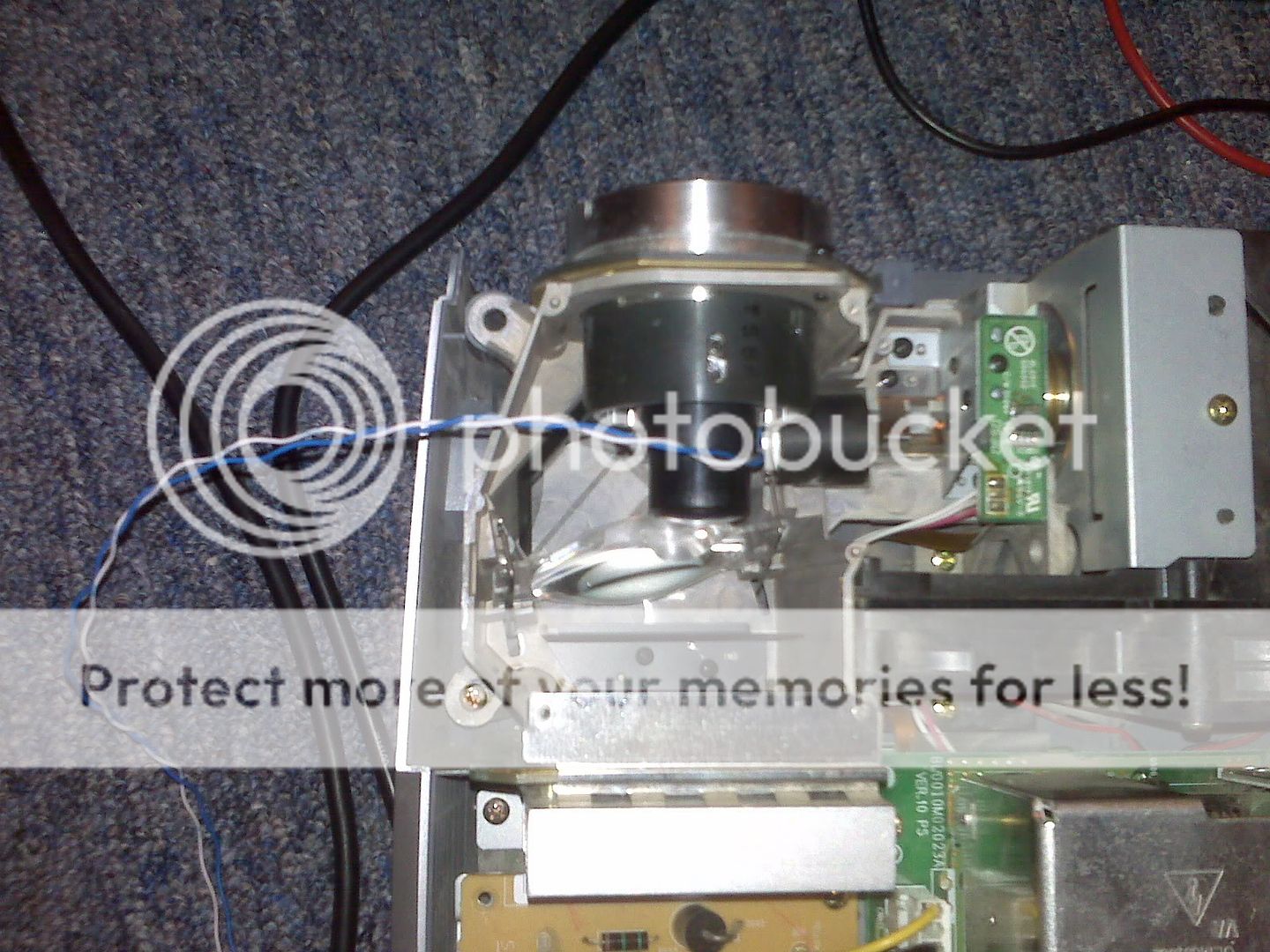
One is Modded Auto HID with ballast and lamp(The one posted here) Stock lamp cage and reflector.
Asking $150
I will post this in the marketplace but I wanted to offer them to followers of this thread first.
The modded one has the internal ballast disabled and the high voltage wires were removed. It can be undone and returned to stock with some small soldering.
One is completly stock No Lamp No Mods
Asking $75
One is Modded Auto HID with ballast and lamp(The one posted here) Stock lamp cage and reflector.
Asking $150
I will post this in the marketplace but I wanted to offer them to followers of this thread first.
The modded one has the internal ballast disabled and the high voltage wires were removed. It can be undone and returned to stock with some small soldering.
Having trouble with bypassinf Hopper xg20
I am new to this post. If some one can be so kind to tell me how to bypass the ballast of the Philips hopper xg20. What I did I got 3 wires one is red 5v then a black one and a white one. It's small wires comming from the main bord to the ballast bord.What does it mean to pull the 5 volt low. Must I solder the red wire to the ground on the main bord directly or ?. What I did already was to put a pin in the connector and take a wire and bring each wire to ground and put power on, but when I swithed the projector on when it was on the white wire and to ground the fuse exploded in the mains suply. Can some one explain to me step by step for Dummies what must I do to bypass the ballast in a Philips hopper xg20 I got the service manuel, pics will be welcomed. you can email me jesus7love3@yahoo.com. Thank you.
I am new to this post. If some one can be so kind to tell me how to bypass the ballast of the Philips hopper xg20. What I did I got 3 wires one is red 5v then a black one and a white one. It's small wires comming from the main bord to the ballast bord.What does it mean to pull the 5 volt low. Must I solder the red wire to the ground on the main bord directly or ?. What I did already was to put a pin in the connector and take a wire and bring each wire to ground and put power on, but when I swithed the projector on when it was on the white wire and to ground the fuse exploded in the mains suply. Can some one explain to me step by step for Dummies what must I do to bypass the ballast in a Philips hopper xg20 I got the service manuel, pics will be welcomed. you can email me jesus7love3@yahoo.com. Thank you.
ounvme is me ") and that wire disables the ballast turn on so theres not 1000V starting pulses zapping you. The wires are called Lamp Lit and Ballast Enable.
and that wire disables the ballast turn on so theres not 1000V starting pulses zapping you. The wires are called Lamp Lit and Ballast Enable.
The projectors with the ballasts built into the power supply and not external need to be modified like this. I need to update the first post of my ballast bypass guide.
and that wire disables the ballast turn on so theres not 1000V starting pulses zapping you. The wires are called Lamp Lit and Ballast Enable.The projectors with the ballasts built into the power supply and not external need to be modified like this. I need to update the first post of my ballast bypass guide.
So I was playing with this thing again and snap there goes my color wheel into 1000 pieces. It was my fault I smacked it pretty good while it was spinning. Since that eliminated the chance of 1 bright LED I started cutting away at the light tunnel. I cut it up to where the lens is. I shined a 100lumen led into the lens and I get a full size picture at 80+ inches in black and white. Now I need to find a way to get either 1 high powered RGB led or find a way to focus 3 leds into the lens.
Hey I've got my used X2 today from flebay. Before I try a lamp, I would like to bypass the thing and try an ohp lamp in there. Could you someone tell me if any 10 ohm resistor will do the job. Because I hve seen the resistors come in different physical size yet all have the same resistance. Does it matter it is a wee tinsy resistor or a slightly bulkier on so long as it is a 10 ohm?
- Status
- This old topic is closed. If you want to reopen this topic, contact a moderator using the "Report Post" button.
- Home
- General Interest
- Everything Else
- The Moving Image
- DIY Projectors
- Infocus X1/X2 Lamp & Ballast Bypass