The BA6247 data sheet does show two Vcc pins, one for the input logic control and one for power output. The logic is run direct from 12v and the output supply pin connected to it by 10R (Akai have used 8.2R...) so I'll check and or change that to be sure.
I will hook the scope onto the resistor and see how it looks when switching, both with the motor and resistive load as the tray loading does seem weak. The slack belts obviously don't help there though.
Thanks again for your input as I have a number of additional things to try that I hadn't thought of")
I will hook the scope onto the resistor and see how it looks when switching, both with the motor and resistive load as the tray loading does seem weak. The slack belts obviously don't help there though.
Thanks again for your input as I have a number of additional things to try that I hadn't thought of
Still struggling with this one...
3 filter caps and a 4R7 in line resistor fitted to the loading and clamp motors - no improvement.
'Zapped' both motors back and forth with a 9V battery - no improvement.
Checked 8.2R Vr resistor to motor drive IC - tested ok but swapped for new one to be sure.
Tested with resistive loads in place of the motors and DC levels switch cleanly with correct voltage.
Measured ripple on the main DC supplies; 12V - 600mV and +5V - 100mV.
Seems high for the 12V rail, so checked the main 3300uF reservoir caps for value and ESR. Both test ok but new ones are on order to be sure.
Run out of ideas for now, so will wait the arrival of the new drive belts and PSU caps, then test again.
If those are regulated rails then that ripple is massive. The 5 volt rail, if that is the main 5 volt supplying the uP etc should have ripple in the single millivolt region or lower.
Raw unregulated supplies will have considerable ripple though.
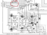
Edit... I've just pulled the circuit for this one.
The output of the two regulators producing the -/+5 volts should be super clean. No visible ripple should be present as measured across the caps at the output of the reg.
The input side of the regulators (the 3300uF caps) will have ripple on them.
I can see lots of simple discrete regulators on that circuit. You need to check they are all OK under load (motor) by using the scope. Check both DC value and ripple. Look for dries on all these parts and the two 78/79 regs.
Check the 180 ohms feeding supplies to these. They look a typical potential problem spot.
Raw unregulated supplies will have considerable ripple though.
Edit... I've just pulled the circuit for this one.
The output of the two regulators producing the -/+5 volts should be super clean. No visible ripple should be present as measured across the caps at the output of the reg.
The input side of the regulators (the 3300uF caps) will have ripple on them.
I can see lots of simple discrete regulators on that circuit. You need to check they are all OK under load (motor) by using the scope. Check both DC value and ripple. Look for dries on all these parts and the two 78/79 regs.
Check the 180 ohms feeding supplies to these. They look a typical potential problem spot.
Attachments
I agree - I work in aerospace test/repair and some of the mil spec stuff are single mV spec with upper limits of 25mV.
The motor drive is fed direct from the unregulated 12V and has over 600mV 100Hz sawtooth ripple, which can't be good.
The output of the 7805 has about 100mV on it but it was replaced with a new one last time I worked on it.
I get a feeling of deja-vu with this as it was my eureka moment last time , so I pulled the regs and fed the rails from external bench supplies. It didn't cure the problem unfortunately.
I'll investigate further and check those 2 x 180Rs.
#Edit - a quick look at the schematic shows mine to be slightly different as its the CD73. This analog board is actually disconnected at present as the digital board works without it and access is easier.
Last edited:
Something is definitely wrong if you are seeing visible ripple on the 7805 output, no two ways about it. It should be super clean.
Definitely stick with that as a line of enquiry. Make sure that you are measuring from the correct ground (junction of the two large reservoir caps). As a test measure to the centre ground pin of the 7805 and check you see zero anything.
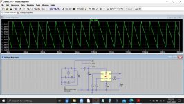
600mv ripple doesn't sound out of the way on an unregulated supply. You would see that with a 3300uF cap and around 230 milliamp load current. I threw those values into a working sim where you can see the 3300uF cap and a 50 ohm load resistor. All the other bits are chopped out.
Definitely stick with that as a line of enquiry. Make sure that you are measuring from the correct ground (junction of the two large reservoir caps). As a test measure to the centre ground pin of the 7805 and check you see zero anything.
600mv ripple doesn't sound out of the way on an unregulated supply. You would see that with a 3300uF cap and around 230 milliamp load current. I threw those values into a working sim where you can see the 3300uF cap and a 50 ohm load resistor. All the other bits are chopped out.
Attachments
I've double checked the +5V ripple at a link wire that is directly off the 7805 output referenced to a 0V test point that's very close to the regulator. Still seeing around 100mV at 100Hz at that point.
It seems I'm going in circles now though... I pulled the +/-5V regulators and a wire link on the +12V rail out last time I worked on it, so I could feed clean supplies from external bench PSUs. That didn't make any difference, so I figured the ripple, although high, wasn't causing the problem.
The micro is definitely going haywire though as I probed the M1, M2, M3 output logic to the motor controller. M3 oscillates furiously when the motors are plugged in but gives clean pulses like M1 and M2 when I unplug them.
You are going to have to measure on the pins of the 7805 directly then. This anomaly has to be resolved in some way.
If your 0V test point is good then you should see zero ripple on the centre ground pin of the 7805. You have to make that test.
If that is OK then you next need to look at the input to the 7805 on its pin. As long as the DC voltage is over around 7 volts and crucially the ripple component doesn't go below that 7 volts then the chip should give a clean output.
(is there any possibility of a ground loop with test equipment etc? Short probe tip and ground lead of scope and touch both to your ground point in the player. The trace should stay clean)
The pins of the 7805 are quite hard to access directly because it's mounted on a heat sink that wraps around it and it's reservoir cap sits in front.
The input supply to the 7805 is derived from the +12V so the ripple on that shouldn't be having a big effect.
The player has a two core mains lead without earth. My scope is a fairly old 20MHz Isotech analogue and has a 3 core lead, so will be earthed.
I plan to pull some of the main supply electrolytics to test and or replace again. I thought I'd fitted good brand ones, Panasonic, Rubycon etc but the two 3300uF turned out to be some obscure make, Hitano. I need to be sure I don't have a problem there in the PSU.
Double isolated for the player should rule out ground loops then... all I can say is don;t deviate from what you can see on the scope.
You have to resolve the reason for what you see, whether it be a fault, a connection error or whatever. Perhaps solder a couple of leads under the board to access the points.
(those and other similar obscure brand caps are always suspect in my experience. We came across a lot of these in TV's and such like back in the day)
I spent some time going through my electrolytics this morning and selecting branded ones with low ESR readings.
I've pulled the ones in the PSU and found 5 that read OK value wise but were 0.3 to 0.4R, so I've swapped them out for better ones.
The Hitano ones test fine so I've put them back for now as the new ones haven't arrived yet.
Confident I have good quality low ESR ones in most locations above 100uF, I checked the ripple again. Still 600mV on the +12V and 100mV on the +5V.
The 600 mv sounds OK for an unregulated rail as I mentioned earlier but the 100mv on the 5 volts output of the 7805 is definitely not fine.
It should be virtually unmeasurable at that point and can only be one of two things. Either a measurement error and either the ground point and/or the point you are measuring to are not what you think they are or there is a real fault which can only be either the regulator itself or the applied voltage (including its ripple component) is taking the regulator below its minimum drop out voltage.
I can't really think of anything else.
Also the grounds are all essentially common and so you should see a super clean - and + 5 volts from the discrete regulators TR30 and TR31 when measured from the ground point you are using now.
I've taken measurements close to the regulators and near the micro just for comparison. They are virtually identical with just a bit more noise near the micro.
I was going to replace the 7805 but noticed it's a fully insulated plastic case and the heat sink a tight fit around it, so there may not be space for a insulating mounting kit for a conventional one.
I need to check what the metal of the heat sink is connected to as it may not matter with the positive rail regulator as the tab is 0V anyway.
It doesn't appear to be a problem with any of the electrolytic caps anyway, which is another thing crossed off.
I took out the old 7805 and replaced it with a brand new one. The original had a 1979 date code on it!
The heat sink wasn't a problem as the mounting tabs are isolated on the PCB. At the same time I relocated the +5V reservoir cap to the rear of the board, allowing unhindered probe access to the regulator pins.
Measuring at the points before, my reading was the same; 100mV. Putting the scope probe directly onto the +5V leg of the regulator and the earth on the metal tab gives a much better 20mV.
TR30 & 31 don't exist in the CD73, so I think you may still be using the CD93 schematic, which does have some significant differences. One that stands out is they use optical devices for the loading tray.
At the moment I've hit a brick wall with this unit (again...) so I think I'll wait for the new loading drive belts and 3300uF caps to arrive before I try to go further.
If all else fails there's always eBay... The KSS151A laser is working and quite a sought after device, so if I can't get it going, at least it will be a valuable source of spares to someone else.
OK, so we are saying that the 100mv ripple was caused by a measurement issue... which is fine as long as you can explain it and be sure there is no underlying issue such as the previous ground point you used having a problem.
So it looks like the rails are OK. If there are doubts with things like loading belts and them causing the tray to perhaps jump at the ends and not fully load/unload then those have to be tried.
It was a CD93 circuit I was going off.
So it looks like the rails are OK. If there are doubts with things like loading belts and them causing the tray to perhaps jump at the ends and not fully load/unload then those have to be tried.
It was a CD93 circuit I was going off.
The previous ground point is a factory fitted test point and only about 30mm from the regulator. There shouldn't be any issue with the solder joints as I removed the digital board completely last year and wicked off all the solder, joint by joint and re soldered it all.
Something is definitely causing the output from the micro to motor driver chip to flap up and down wildly when the tray loads but I'm still skeptical that the new belts will solve it.
If it can be persuaded to move to the next phase of loading by cycling the power, which is the tray clamping phase and that mechanism exhibits the same oscillating. That is purely gear driven though, so isn't plagued by slack rubber belts.
It also continues to oscillate and eventually reverts to the previous stage and unloads the tray. If the power is cycled a couple of times before that happens, the tray clamps down and the disc plays.
It is most bizarre to observe and there is video on You Tube of another CD73 doing the same thing.
You need to investigate this ground then. Try and see for yourself what it actually connects to in the player.
If it is meant to be the same ground as the regulator uses then there should be continuity between those points and that in turn means the scope result should be similar using either.
If it is meant to be the same ground as the regulator uses then there should be continuity between those points and that in turn means the scope result should be similar using either.
The digital PCB has a copper ground plane on it's upper surface. This is connected to the star earth at the 2 x 3300uF caps on the underside by a tab that is soldered through the board at one of its mounting holes.
The 0V test point that I thought connected directly to the regulator is actually soldered to the ground plane on the top surface. This means it is electrically around 6 inches from the regulator's 0V pin.
The ground plane isn't connected to the chassis at any of the board mounting points, other than the one with the through board tab, presumably to prevent earth loop problems.
The distance shouldn't make any difference, its only in very high frequency and RF design that it would. If you think that copper ground plane should be electrically connected to the regulators ground pin then it needs investigating.
It is something you need to have in front of... so I can only guess but it all sounds a bit weird with that ground.
See if anything else connect to that ground plane and if so then find it on the circuit and see if that should be connected to the regulator ground.
Don't discount something like a bad earth and remember all the issues Philips players have with those griplets and so on.
I will investigate the ground plane connection further. There is a PCB connector from the PSU star earth with 5 or 6 wires that go off to various points on the board, so the ground plane isn't used to distribute power.
The ground plane seems to be a shield connected at one point to the PSU. I'll make sure that connection is good.
At the moment I'm having a break from it, having a drink and listening to my (not as nice) Pioneer CD player. That does at least work though!
The ground plane seems to be a shield connected at one point to the PSU. I'll make sure that connection is good.
At the moment I'm having a break from it, having a drink and listening to my (not as nice) Pioneer CD player. That does at least work though!
- Home
- Source & Line
- Digital Source
- Akai CD-93