Hi i have recently got 2 Arcam Alpha CD5+ Cd players.
Both were broken and free but i have fixed there problems, the normal drive tray teeth sheared issue.
Seen as these have supposedly very good mechanism and DAC (TDA1541a) i thought it would be worth trying to do a bit of DIYing on one of them.
I Hope in the future to reclock one but for the time being i was thinking of cap and op-amp swapping.
Has anyone got any experience with these or anthing similar.
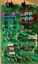
I have included a picture below to show what i am working on.
I was going to start of replacing the Power supply caps in the red box they are bog standard rubycons 100 and 1000uf 25v. Should i black gates these and should i stick with the same values? Trouble is the black gates are larger for the same value.
The opamps in light blue are NE5543 and someone advised me to replace them with OP27GP which are also the ones used within the green square.
The light grey output caps are rubycon non polar 100uf 16v. I want to replace tehm with some blackgates as well but i cannot seem to find and non polar black gates in the u.k. Could i fit normal black gates (N or NX)? or do i need non polar.
Any help or advice greatly appriciated
Fil
Both were broken and free but i have fixed there problems, the normal drive tray teeth sheared issue.
Seen as these have supposedly very good mechanism and DAC (TDA1541a) i thought it would be worth trying to do a bit of DIYing on one of them.
I Hope in the future to reclock one but for the time being i was thinking of cap and op-amp swapping.
Has anyone got any experience with these or anthing similar.
I have included a picture below to show what i am working on.
I was going to start of replacing the Power supply caps in the red box they are bog standard rubycons 100 and 1000uf 25v. Should i black gates these and should i stick with the same values? Trouble is the black gates are larger for the same value.
The opamps in light blue are NE5543 and someone advised me to replace them with OP27GP which are also the ones used within the green square.
The light grey output caps are rubycon non polar 100uf 16v. I want to replace tehm with some blackgates as well but i cannot seem to find and non polar black gates in the u.k. Could i fit normal black gates (N or NX)? or do i need non polar.
Any help or advice greatly appriciated
Fil
Attachments
I think the Op amps are 5534. I would fit some sockets and have fun trying differnt types... I really like the OPA604 and OPA176 (if you can get) as drop ins for the 5534. 627/637 is good 2 but expensive... AD825 on adaptor boards... Do a search and you will read for two days from the posts on this forum...
I found OP27G a little forward sounding but it is all about taste...
You can use polarised caps back to back (negative joined) to make a non polar cap, the combination cap will be the voltage rating of the 2 caps added but it is like parallel resistance, ie half the capacitance.... 2 x 25 V 100 MFD would make a 50 V 50 MFD non polar cap....
Cheers man,
I have only just got into the diy thing, half way through building some gain clones and want a decent source to use with them.
What about the other op amps, should i just change the 'purple' ones or the green as well. Sockets sound like a good idea though.TA
Also for the 'red' caps what you you think would be a good replacement. Black gate standard or something else, i think they are a bit big in the same values.
I have also read to i can remove the output muting transistors to help sonics so that might be my starting point.
Can you think or anything else that i might do, i have heard a lot about using bypass caps but dont know exactlly what that means. Is this like the snubber caps in carlosfm gainclone amp and what would in mean doing to implement it here.
Maybe that to complicated
Anyway thanks for replying.
The site is a little quiet for the past few days. Easter holidays maybe.
My fave not too diffycult upgrades are:
Soft recovery diodes
Good DC blocking output caps. Cerafine, Starget, Black gate etc.
Better op amps
Messing with the clock crystal. Yours already has arubber grommet which helps a lot. Lead tape and a grommet is even better...
WRT to the op amps... fit sockets and change on set at a time and listen carefully. do not do too much at once so yu can decide which steps you like and dont like.
By passing caps refers to using lower value non electrolytic caps across higher value electrlytics on the PSU to reduce the ESR of the big caps...
0.1 MFD poly caps are a good start. You could easily do this on the PSU caps on the board you are looking at. (the 100 and 1000 mfd) as well as across the op amp psu pins to ground.
In comparison to most guys on this forum I am quite dumb. You will get better responses yet I am sure. There are some folks who know the Arcam stuff and Philips chipsvery very well. Trust me, there are many things you can do to this player.
Non oversampling may be one of them.....
Thanks very much mate,
You have been very help full i feel more confident in attacking it now.
Like you said i am sure there is a lot i can do with this machine and i think the fact i have got two makes it even more fun really since i can keep one stock and as i change things have a constant point of referal to see how things are coming along.
From the sounds of it the Avondale tuned version of thiscd player is a giant killer machine its just i dont have the £375 to get it done. And i honestly would like to do the thing myself.
I am learning a lot at the moment and its fun
cheers mate
There's loads of info on tweaks for this player archived at
http://pinkfishmedia.net/forum/forumdisplay.php?s=&forumid=8
I removed all the analog filtering, and replaced the digital filter with a nonOS/reclocker module from NET Audio.
http://www.net-audio.co.uk/tda1541nos.htm
I'd try the CD player with all four big caps removed, tune elsewhere, and then add big caps to taste. Sanyo SEP caps are very good.
The opamp feedback resistor type has a big influence on the sound, it might be an idea to start here. Try 0.5W carbon from farnell or Audio Note tantalums. You can solder them directly onto the opamp pins to preserve the PCB tracks.
You can also bias the opamps into class A with a Siliconix J511 diode across pins 6 and 7 (IIRC).
Yeah i have already spoke to www.net-audio.co.uk
There reclock/NOS board only works on the 5 not the 5 plus.
Well that what Dave told me if you know different that would be cool.
"I'd try the CD player with all four big caps removed, tune elsewhere, and then add big caps to taste. Sanyo SEP caps are very good"
Sorry you lost me there, remove all caps and tune elsewhere, what does that mean. Like i said i am a big of a beginner at this. Need more spoon feeding.
As for the Sanyo Sep are they avaible in the sizes i need? In the u.k. i can only find 56uf as opposed to the 100uf and 1000uf i need.
Anyway thanks for the reply
I think my Arcam was the Plus model. No problems noted.
There are 4 x 1000uF caps on the audioboard IIRC. Try removing them altogether, then tweaking the rest of board, then investigating replacements for the 4 x 1000uF.
FIddling about with my nonOS DAC, it seems the smaller the cap before the regulators the better. Better timing and more slam from a SAnyo SEP 330uF 16v than a Pansonic FC 3300uF 35v.
Farnell have a selection of SEPs:
http://uk.farnell.com/jsp/endecaSea...4&Ntt=sanyo+SEP&Nty=1&N=401&Ntk=gensearch&y=5
You can make the Net Audio NOS/Reclocker work in this cdp - if you get the cheaper version without onboard crystal - and feed it from the Arcam's clock. However, it is probably not worthwhile here as this player already has reclocking of all lines anyway.
If you don't need the digital o/p - then you can disable it and its use of the 74hc175. It's not a good idea to reclock so many signals in one package.
If you don't need the digital o/p - then you can disable it and its use of the 74hc175. It's not a good idea to reclock so many signals in one package.
You can make these changes.
First change all diodes i rectification to schottky type (1A 60V), than all caps in power supply of analog section change to Black Gate , in digital power supply you pull out all caps including those ceramic type and put back only Sanyo OsCon-s. Output coupling caps are not so critical in their capacitance values. Probably the best results will be to replace them with polypropilene (Mundorf) caps of let´s say 4.7-10uF.
Change the OP-s to BB Opa 604.
I have heard that the best way to make this board sound better in to to a do a zero oversampling mod. which can apparently can be done by rewiring rather than needing anything extra.
Has anybody done this mod and could they describe how it is done.
I have found some very basic descriptions on tweakers asylum but it was way to general for me to fully understand
Has anybody done this mod and could they describe how it is done.
I have found some very basic descriptions on tweakers asylum but it was way to general for me to fully understand
Easy peasy....
Isolate pins 1, 2 and 3 of the DAC chip TDA1541A from the pcb by either breaking tracks (yuk) or some other means...The DAC pins 1,2 and 3 must not be connected to anything... On my Mission CDP I have removed the IC, fitted a socket from which I removed pins 1,2 and 3 so the IC pins float above the pcb. Now solder wires linking the IC pins 1,2 and 3 of the TDA1541 to pins 1, 2 and 3 of the SAA7220 filter chip. Non os mod done.....
There is only one problem with this.. You have now defeated the muting function of the SAA7220 as you have bi passed it. To restore mute, a link needs to be made between the SAA7220 and the decoder chip. On the Alpha 5 I doubt this is a SAA7210 but something else and I do not know what pins to link to restore mute.
It will work without but you will hear sections of disk being played while starting play and skipping as well as pausing the player. It is just odd sounding but I believe harmless.
Others may well know the decoder chip type and the required pin links to restore muting after non o/s.
Forgot to say, if you fit a socket in place of the DAC chip but do not remove pins and into that socket you plug another socket but this one with the pins 1,2 and 3 removed you will be able to reverse the change without much soldering by removing the doctored socket and plugging the DAC back in. this may allow for faster AB comparisons 2. Once you know what you like minimise the use of sockets though!!!
On my mission I use a different arrangement, harder to explain but I effectively have made it so that I have a 3 wire fly lead that plugs the DAC pins to their original connections or to the SAA7220 pins 1,2 and 3 allowing very quick AB of non O/S vs 4 x os....
On my mission I use a different arrangement, harder to explain but I effectively have made it so that I have a 3 wire fly lead that plugs the DAC pins to their original connections or to the SAA7220 pins 1,2 and 3 allowing very quick AB of non O/S vs 4 x os....
Hiya,
I use the following method with the Arcam Alpha5+ and it sounds great! There are no glitches with muting etc done this way.
If you have the 1541 A then in the mode it is used pin 4 is not required - connect it to the adjacent ground pad ground (i think it's pin 5 from memory)
Non over sampling:
lift or cut pins 1,2,3,15,16,18 of SAA7220 from the board .Join the
vacated holes with wire thus: 1 to 18 2 to 16 3 to 15.
Hope that helps
David
If you have the 1541 A then in the mode it is used pin 4 is not required - connect it to the adjacent ground pad ground (i think it's pin 5 from memory)
What is the role of pin 4? Does it have anything to do with muting? If not I can only assume the muting is done on the decoder chip, not the filter as standard.
Juancho's non o/s method seem elegant and can also be done with a stack of two or even 3 IC sockets for quick AB. Remove the pins that need "lifting" and plug the chip into this socket (1). use another socket (2) and bridge the pins on this socket with wire links at the bottom of the socket. Fit a socket (3) to the PCB. using all 3 sockets is non o/s and if you remove 1 &2 and plug chip into socket 3 for std 4 x o/s....
Again, once you know what you like use as few sockets as possible.
Thanks for the help guys. So all work is done on the SAA7220 apart from one line on the tda1541.
Just so we are all clear one what to cut can you possibly look at these pdfs of the parts to double check which lines to dissconnect.
http://www.alldatasheet.com/datasheet-pdf/view/PHILIPS/SAA7220.html
http://www.alldatasheet.com/datasheet-pdf/view/PHILIPS/TDA1541A.html
I really dont what to trash the player for no good reason!!
Well i guess the search for higher fidelity is a good reason but you know what I mean
Fil
Cheers for all the help guys
Hiya,
If you can hang on a little bit I will take the board out of my Arcam and double-check for you.
One thing which probably won't bother you as you want to use the built in DAC is that you lose the digital out when converting to NOS.
I'm afraid I could never get the datasheets for the saa7220 or TDA 1541 so did this mod 'blind' but the person who told me it is very knowledgeable /reliable.
Cheers
David
- Status
- This old topic is closed. If you want to reopen this topic, contact a moderator using the "Report Post" button.
- Home
- Source & Line
- Digital Source
- Upgrading Arcam Alpha CD5+ Analogue Board