adfinni -
Run the clock off the +12v reg. Or ideally run it from a dedicated +12v super reg (which I have done).
And place the other two +/- 12v regs really close to the op amps.
All my bypassing is done with silver wire, not sure how much difference it would have made but I used it anyway
You are also better off getting 3 5V super regs too mate (if you have the cash). One for digital 5v one for analogue 5V and one for the clock reference 5v (DAC).
The standard 7805 can be left in to power the microprocessor.
It may sound a lot of work and money but I find it best to think ahead to the final goal mate. Also when you change the regs and isolate all the rails the caps will need upgrading at the relevent points to maximise the benefits.
adfinni said:Also, how do i power the superclock2 by using the voltage rails in the CD63 itself
Thanks again
Hi adfinni,
Do not, by any means, run the clock off the +12V!!!!

Shame on you Brent, thought you'd know better by now.
But besides this small glitch, his other tips can be trusted.
The +12V is used to feed the (analog...) opamps. You should tap power from C813, that powers
the digital +5V. A dedicated small PSU is even better.
You need our custom wound toroidal tranny
BTW, your non-silver solder will do fine.
Regards,
Ray.
Looks like most of your questions were answered by the others, but I'll chip in too
I use Russ Andrews Oak Cone Feet and they work an absolute treat - you'll get a more solid rhythmic sound, just as he says. You may find this solves the common problem of 'hi-fi' bass - it will become vastly more realistic. I've not compared with other cones e.g. al. Use three for obvious reasons. You should be using a rack too.
Really the wire is the smallest change to sound, but as Rowe says you can use silver and be happy to have something fancy in there. If you want something sonically fairly benign though use a strand of CAT5 network cable. The old solder is easier to use, and the silver-loaded stuff is harder to use, as is leadfree. It's a bit cr@p in fact.
As Brent said, you can use the 12v but it won't sound anywhere near as good as it should. I don't think 5v is enough to power it. A better option could be the would-be '5v' line before it enters the regulator, what do we think about that?
If you want help building a psu I can help, as I am a beginner too, and I won't assume you know too much. I made a psu for my clock. Just needs a very small transformer, a bridge or some diodes, some caps and you're about there! It's not too hard to do.
Simon
adfinni said:Il look into getting some new feet asap, but do you have any recommendations for spikes before i do? 3 or 4 spikes ?
I use Russ Andrews Oak Cone Feet and they work an absolute treat - you'll get a more solid rhythmic sound, just as he says. You may find this solves the common problem of 'hi-fi' bass - it will become vastly more realistic. I've not compared with other cones e.g. al. Use three for obvious reasons. You should be using a rack too.
Il try and get these caps removed asap, but what cable do you recommend i use to bridge the gaps, and would my non-silver antex solder be satisfactory (i may try to get some old lead solder off ebay)
Really the wire is the smallest change to sound, but as Rowe says you can use silver and be happy to have something fancy in there. If you want something sonically fairly benign though use a strand of CAT5 network cable. The old solder is easier to use, and the silver-loaded stuff is harder to use, as is leadfree. It's a bit cr@p in fact.
Ok il probably go for the superclock 2, and audicom super-regs +5v, 12v, and -12v. Are these easier to fit into the player?
Also, how do i power the superclock2 by using the voltage rails in the CD63 itself
As Brent said, you can use the 12v but it won't sound anywhere near as good as it should. I don't think 5v is enough to power it. A better option could be the would-be '5v' line before it enters the regulator, what do we think about that?
If you want help building a psu I can help, as I am a beginner too, and I won't assume you know too much. I made a psu for my clock. Just needs a very small transformer, a bridge or some diodes, some caps and you're about there! It's not too hard to do.
Simon
SimontY said:A better option could be the would-be '5v' line before it enters the regulator, what do we think about that?
That would be C813!
Sorry, couldn't resist....
6h5c said:
That would be C813!
Sorry, couldn't resist....
Hehe, well I wasn't gonna start looking in the service manual, and I certainly can't remember part location numbers! At least it confirms what I thought!
edit: I think you threw me, Ray, when you said "digital 5v+", as there is only one 5v reg in a stock player I think.

SimontY said:
.............If you want help building a psu I can help, as I am a beginner too, and I won't assume you know too much. I made a psu for my clock. Just needs a very small transformer, a bridge or some diodes, some caps and you're about there! It's not too hard to do................
Simon
Hi Adfinni,
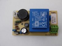
I bought a load of these PSUs of EBAY. They fit just nicely behind the display panel.
These are as basic as you need :- transformer, rectifier (yes-I know it's a cheap bridge!!), smoothing caps and regulator.
( I have to make a slight mod as these are set to 6v - I will be setting to 9v then using a super-reg to +5v )
Layout is not critical so perf-board will do, if you build one youself.
Maplin also sell a small board for an adjustable psu ( part no. VE58N )- just connect a small transformer ( eg Maplin part WB01B ) and set the volts to +5v.
Andy
Attachments
poynton said:I bought a load of these PSUs of EBAY. They fit just nicely behind the display panel.
Hi Andy, how much did you snuffle those little babies up for?

I
 Ebay...
SimontY said:edit: I think you threw me, Ray, when you said "digital 5v+", as there is only one 5v reg in a stock player I think.
/hehe, this time I got there first


SimontY said:
Hi Andy, how much did you snuffle those little babies up for?
I
Simon, got the sick bag ready????

I paid £15 for 10 inc. postage! HeHe
Andy
poynton said:Simon, got the sick bag ready????
I paid £15 for 10 inc. postage! HeHe
Andy

Classic Ebay bargain!
My fave so far that I got was 128 7" bass drivers for about £70.
Altho my 2kva isolation tx was a good buy too, think that was £35, or maybe less.
SimontY said:
My fave so far that I got was 128 7" bass drivers for about £70.
Ok - I have to ask - what on earth do you do with 128 7" bass drivers???
( apart from reselling them singly on Ebay for £5 each )
poynton said:Ok - I have to ask - what on earth do you do with 128 7" bass drivers???
http://www.diyaudio.com/forums/showthread.php?s=&threadid=72408 and particularly
http://www.diyaudio.com/forums/showthread.php?postid=831232#post831232
I'm having a go at making my speakers into 3-way by rolling off the current mid/bass section and introducing some extra cabs loaded with these babies. 8 per speaker isobaric push-pull is what I am knocking up right now, and it could be ok, certainly should take a LOT of power.
Also, we modified 6 (removed cones, added steel bar across frame, blocks of wood etc.) to use as floorshakers in my friends bassment. We also used 4 in his 'bar' area to bring up the midrange and upper bass in there, just mounted in-wall.
So that's 10 down and possibly 16 to use in the current project...
Yes, I have considered this and will probably try a few and see if anyone takes them. They're decent enough units and I can sell them with a suggested cabinet or even plans, so I think it's a nice product for a fiver. And good markup!(apart from reselling them singly on Ebay for £5 each)
Ray quote
The Audiocom clock runs off of a +9V to +18V supply.
I gave the option to run it from the standard 12V cct short term.
I have my clock running from a 12V audiocom reg supplied from the now barely used +20V rail.
Do not, by any means, run the clock off the +12V!!!!
The Audiocom clock runs off of a +9V to +18V supply.
I gave the option to run it from the standard 12V cct short term.
I have my clock running from a 12V audiocom reg supplied from the now barely used +20V rail.
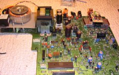
What's the PCB floating above the HDAM cans? Some PSU filtering?
No, this is a simple LC low pass filter (ca. 50kHz/12dB).
All the modifications are according to Gerald Gessner. The audio part consists just 50% of an OPA2134 followed by the LPF.
Franz
Franz G said:
No, this is a simple LC low pass filter (ca. 50kHz/12dB).
All the modifications are according to Gerald Gessner. The audio part consists just 50% of an OPA2134 followed by the LPF.
Franz
Hi.
How close does the tray come to the Tx / board??
Do you have a link for this mod??
Andy
6h5c said:
.................It is an exact copy of Thorsten's circuit.................
Hi.
Did you keep any of the original filter after the DAC or did you change everything as per Thorsten's circuit????
Andy
poynton said:Hi.
Did you keep any of the original filter after the DAC or did you change everything as per Thorsten's circuit????
Andy
Hi Andy,
I took out the resistors directly at the outputs of the DAC and connected it to Thorstens filter instead. The circuit sounds very good, but I have some HF noise present in my tweeters. I'm now figuring out if it is radiation from my nearby clock PCB, or because the circuit uses only one output and thus it is not cancelled out in some way.
Franz G said:No, this is a simple LC low pass filter (ca. 50kHz/12dB).
All the modifications are according to Gerald Gessner. The audio part consists just 50% of an OPA2134 followed by the LPF.
Franz
Franz,
Do you have a schematic of the passive circuit you use?
Is there any noise residue with this passive circuit?
Regards,
Ray.
- Home
- Source & Line
- Digital Source
- Marantz CD63 & CD67 mods list