Now that you mention it, the decoder could very well be the culprit. I believe I read something in the past about it's CRIN/CROUT pins specifically being designed for use with a crystal. That's probably why Marantz had to go through all the trouble of adding those extra R/C at the pins to make it work with the external signal. Maybe the rise/fall times are just too steep and the RC network tunes this down a bit. I only clocked the CD67 decoder directly, and I assumed I would work like that with a 63 as well...
Ray
Ray
All those low-noise regulators will not help against the high-frequency square wave that is output by the DAC itself... it's the nature of the beast, so to speak.
The analog filter is needed to create a sinewave shaped signal out of this pulse-width modulated output, because it's nowhere near analog. If you bypass the filter, all kinds of higher-order harmonics will enter the system and this will create all sorts of distortion and intermodulation products. Not good...
But, depending on the system, you may or may not hear the negative side-effects of this.
Good luck with The Flea's
Ray
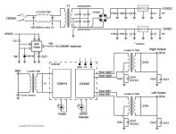
regarding the 5 MHz in the output of the DAC, I am thinking to use a transformr with very separated primary and secondary in order to completelly eliminate the 5 MHz and leave only the audio in the pWM signal. Does someone foresee a problem with this aproach?
thanks
regarding the 5 MHz in the output of the DAC, I am thinking to use a transformr with very separated primary and secondary in order to completelly eliminate the 5 MHz and leave only the audio in the pWM signal. Does someone foresee a problem with this aproach?
thanks
5 MHz in the output of the DAC

No, that shouldn't be a problem. The transformer acts as a low-pass filter due to the nature of inductance (impedance rises with frequency...) so the audio-signal will pass without problems and most of the the HF noise will be blocked. The transformer will also do the summing of the symmetrical outputs. Here's an example:
Attachments
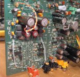
R124 and 125 form a potential divider from the 5v rail near the servo to create a 2.5v vref. If the values are incorrect the vref will be wrong.
What voltage are you getting at the junction of the 2 resistors? Without the vref, you will have no radial, focus or laser
Now the CD start spinning ... Horeee
R 124 and R 125 value was 2.49volt and 2.49 volt
Looks like i must desolder some caps beside HDAM
i tried AD823AN but the sound look so aggressive.
than come back to original, next i will try LM6172IN
Attachments
Now the CD start spinning ... Horeee
R 124 and R 125 value was 2.49volt and 2.49 volt
Looks like i must desolder some caps beside HDAM
i tried AD823AN but the sound look so aggressive.
than come back to original, next i will try LM6172IN
Give OP275 or LM4562 (LME49720HA) a chance
During the process of modding my 2nd CD63 I accidentally blew up Q106 (Dual opamp TCA0372). Actually there was an minor explosion blowing off the top of the IC leave big hole behind !!! I could also see sparks
This happened after I changed some of the caps and I suspected that there was a short circuit somewhere caused by the remains of either the left over solders or the copper wire legs of the caps leaving behind on the PCB.
Luckily when I switched on the player it could start up but only could not read any CD. The drawers could open and close. I hope it will work again when I change the damaged IC. I have just ordered one from the Bay for about £5.
In future I will ensure the inside of the PCB are clear before switching on the power.
Hi All,
My CD53 door wheel teeth are broken. Can anyone please suggest a good door eject wheel?
Thanks
Badri
My player's Door eject wheel is broken. can it be replaced? Or do i need to change the whole thing? If any available in ebay can you please the link? Thanks in advance.
Thanks
Badri
My player's Door eject wheel is broken. can it be replaced? Or do i need to change the whole thing? If any available in ebay can you please the link? Thanks in advance.
Thanks
Badri
No need to bump its not polite!!! I'm sure many of the helpful people who regularly assist with this thread are very busy with Xmas preparation!!!!
Personally never seen or heard of a broken one and never seen them for sale. How on earth did you manage that??
No need to bump its not polite!!! I'm sure many of the helpful people who regularly assist with this thread are very busy with Xmas preparation!!!!
Personally never seen or heard of a broken one and never seen them for sale. How on earth did you manage that??
Merry christmas and Happy New Year to all. Thanks UV101. Its not my intention to bump. I bought the player as it is. Now when I press the eject buttton the door got stuck in the middle. I checked the reason, most of the teeth in that gear worn out. Now I am manually pulling out the door to change a cd. I am trying to find a replacement.
Last edited:

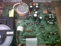
Is that picture your player? If so you have completely bypassed the HDAM and linked the output stage output direct to the output. If the output phonos are still connected to the PCB, you will still have the muting transistors in circuit and by linking those caps out will be feeding the sound into the output of the HDAM??
Std is
Dac > Opamp and filter > HDAM > DC blocking caps (silmics) > muting > phono sockets
Ideally you want
Dac > Opamp and filter > phono sockets
It looks like you have achieved a quite remarkable hybrid that I've never seen previously
DAC > opamp and filter > phono sockets > muting > links where the DC blocking caps were > HDAM (backwards and without power)
Either fit new sockets directly on the end of the output from the Opamp and filter section or removed the components that are now feeding the audio backwards into the muting stage, linked out caps and Dead HDAM!
Grab the manual and work out the signal path!!
During the process of modding my 2nd CD63 I accidentally blew up Q106 (Dual opamp TCA0372). Actually there was an minor explosion blowing off the top of the IC leave big hole behind !!! I could also see sparks
This happened after I changed some of the caps and I suspected that there was a short circuit somewhere caused by the remains of either the left over solders or the copper wire legs of the caps leaving behind on the PCB.
Luckily when I switched on the player it could start up but only could not read any CD. The drawers could open and close. I hope it will work again when I change the damaged IC. I have just ordered one from the Bay for about £5.
In future I will ensure the inside of the PCB are clear before switching on the power.
Returned from holiday yesterday and this morning I changed the burnt out opamp Q106 (TCA0372). The CD63 works like a charm again. Actually I did not do anything apart from cleaning up the entire PCB to ensure there is no left over solder. Now I can continue with the remaining modding work
- Home
- Source & Line
- Digital Source
- Marantz CD63 & CD67 mods list