Re: Marantz HDAM D.O.S.
You will find that it has been done....
Read previous posts.
mm2 said:
Marantz HDAM is D.O.S. too, but why is it so bad ?
Whats about tweaking the Marantz HDAM ?
Cheers
You will find that it has been done....
Read previous posts.
How to test a DOS before installation
I have just finished building this DOS.... Did you test the DOS before installing it on the CDP or did you connect it inside the CDP from the beguinning ?
I would like to test mine before it replaces the CD53 opamps and would apreciate some guidance.
Regards
Ricardo
Hi Stevestvnharr said:
D.O.S. - everyone with an eligible player should have one!!!!!!!!! This is simply the most profound improvement in audio quality I have experienced in 15 years of being serious in this hobby. AT LAST, most all, if not all, of the music on the disc gets played and enjoyed. Absolutely fantastic!!!!
I have just finished building this DOS.... Did you test the DOS before installing it on the CDP or did you connect it inside the CDP from the beguinning ?
I would like to test mine before it replaces the CD53 opamps and would apreciate some guidance.
Regards
Ricardo
You will find that it has been done....
Read previous posts.
which Posting # do you mean ?
Thanks
Regards
mm2 said:
which Posting # do you mean ?
Now this is really difficult..... try searching the thread by "discrete" and look for Ray´s work.
Re: How to test a DOS before installation
Ricardo,
My only power source was the player, and I didn't really know what any voltage should be other than the rail voltages, so I basically just hooked it up and hoped it would work. Since you are bypassing everything after the dac and going staight to the output rca, you shouldn't have to replace anything before connecting up, other than removing the resistors coming out of the dac and disconnecting the rca's from the previous connections. Mounting the DOS can take a fair bit of time, depending on how you do it. Maybe I can take a pic or 2 and try to post them some time.
Hope this helps.
Steve
RCruz said:
Hi Steve
I have just finished building this DOS.... Did you test the DOS before installing it on the CDP or did you connect it inside the CDP from the beguinning ?
I would like to test mine before it replaces the CD53 opamps and would apreciate some guidance.
Regards
Ricardo
Ricardo,
My only power source was the player, and I didn't really know what any voltage should be other than the rail voltages, so I basically just hooked it up and hoped it would work. Since you are bypassing everything after the dac and going staight to the output rca, you shouldn't have to replace anything before connecting up, other than removing the resistors coming out of the dac and disconnecting the rca's from the previous connections. Mounting the DOS can take a fair bit of time, depending on how you do it. Maybe I can take a pic or 2 and try to post them some time.
Hope this helps.
Steve
Re: Marantz HDAM D.O.S.
Let me help you out a little bit.
The Marantz output stage, with HDAM, is not necessarily bad, as it does output music. But the music it puts out is severly limited in low level detail and ambient information.
The Marantz HDAM, Hyper Dynamic Analog Module, is just the little discrete opamp circuit under the copper shield cap and consists of 6 semi-conductors, 8 resistors, 5 diodes, and 1 capacitor. This is the HDAM in the 8400/8260/8001/7001.
The whole output stage also consists of the low pass filter, containing many many parts, the current amplifier, also with many parts, and the musically damaging muting circuit.
Prior to my DOS project, I replaced every single cap on the board, other than the little ceramic capacitor under the copper shield, and bypassed the muting circuit. This did provide some small improvement. You could also replace every resistor, as does Underwood Wally of Underwood Hi-Fi in his mod package.
However the simple DOS, consisting of the passive low pass filter and Class A buffer doesn't filter out any of the music and amplifies all of it! It is by far the biggest audio improvement I have ever heard in 15 years of audio, swapping amps, changing players, cables, speakers, etc.
The most daunting part of the DOS project is having a pcb to work on. And at the moment, there is no easy solution there, just more diy.
Hope this helps.
Steve
mm2 said:
Marantz HDAM is D.O.S. too, but why is it so bad ?
Whats about tweaking the Marantz HDAM ?
Cheers
Let me help you out a little bit.
The Marantz output stage, with HDAM, is not necessarily bad, as it does output music. But the music it puts out is severly limited in low level detail and ambient information.
The Marantz HDAM, Hyper Dynamic Analog Module, is just the little discrete opamp circuit under the copper shield cap and consists of 6 semi-conductors, 8 resistors, 5 diodes, and 1 capacitor. This is the HDAM in the 8400/8260/8001/7001.
The whole output stage also consists of the low pass filter, containing many many parts, the current amplifier, also with many parts, and the musically damaging muting circuit.
Prior to my DOS project, I replaced every single cap on the board, other than the little ceramic capacitor under the copper shield, and bypassed the muting circuit. This did provide some small improvement. You could also replace every resistor, as does Underwood Wally of Underwood Hi-Fi in his mod package.
However the simple DOS, consisting of the passive low pass filter and Class A buffer doesn't filter out any of the music and amplifies all of it! It is by far the biggest audio improvement I have ever heard in 15 years of audio, swapping amps, changing players, cables, speakers, etc.
The most daunting part of the DOS project is having a pcb to work on. And at the moment, there is no easy solution there, just more diy.
Hope this helps.
Steve
There is nothing wrong with the HDAM itself.
It's the other stuff, ic's filter etc, that does the damage.
It would be possible to remove the ics and modify the HDAM.
This has been suggested previously in the thread.
However, modifying the HDAM and retaining the rest would not achieve a significant improvement.
Previously in the thread, I experimented with a simple tube amplifier after the filter. The results from this were on par with Ray's discrete output - nothing short of amazing in the detail etc compared with standard.
Andy
DOS testing
Just finished my DOS for the D53.
As I will have to do major surgery in the CDP just to be able to locate the DOS inside, (I will need to remove the opamps, opamp PSU and caps to free some space, drill the back panel to fit some RCA´s, fix the big output caps)...
So I would like to test it before instalation.
I just built a bench regulated +-15v psu to fire the DOS before instalation, but I do not know what to feed in the input and what to expect in the output.
Would you explain a simple procedure to test the DOS ?
Regards
Ricardo
Hi Ray6h5c said:
Cool! And another one playing...
Just finished my DOS for the D53.
As I will have to do major surgery in the CDP just to be able to locate the DOS inside, (I will need to remove the opamps, opamp PSU and caps to free some space, drill the back panel to fit some RCA´s, fix the big output caps)...
So I would like to test it before instalation.
I just built a bench regulated +-15v psu to fire the DOS before instalation, but I do not know what to feed in the input and what to expect in the output.
Would you explain a simple procedure to test the DOS ?
Regards
Ricardo
Re: Re: How to test a DOS before installation
This is a bold move that I would like to avoid.
Removing the resistors after the dac can only be done after removing the spower feeding it.
I must also rearrange some internal psu´s to make space for the DOS.
All this involves a lot of work so I would like to be sure the DOS is working before instalation.
Regards
Ricardo
Hi Stevestvnharr said:
I basically just hooked it up and hoped it would work.
This is a bold move that I would like to avoid.
Removing the resistors after the dac can only be done after removing the spower feeding it.
I must also rearrange some internal psu´s to make space for the DOS.
All this involves a lot of work so I would like to be sure the DOS is working before instalation.
Regards
Ricardo
Re: DOS testing
You can simply take the input to where it goes without disconnecting anything else and run a temporary power supply and output connection.
This will enable you to test the DOS without destroying your cdp.
Andy
RCruz said:
Would you explain a simple procedure to test the DOS ?
You can simply take the input to where it goes without disconnecting anything else and run a temporary power supply and output connection.
This will enable you to test the DOS without destroying your cdp.
Andy
Both circuits have a high input impedance - the DAC should drive both without a problem.
Leave the op-amp stage connected and connect the DOS up as well (connect wires to the DAC end of the first 10k resistors on each DAC o/p. Connect the o/p to a separate set of RCAs and you can even compare the two....") When you're happy that it works (and sounds better), you can start removing the op-amp stage. You need only isolate it from the input, output and power supply - you don't have to strip it right out.
When you're happy that it works (and sounds better), you can start removing the op-amp stage. You need only isolate it from the input, output and power supply - you don't have to strip it right out.
Talking about the HDAM, it is an op-amp made of discrete components, configured as a buffer, which means the output is tied directly to the inverting input, with the non-inverting input taking the signal. 100% NFB. Using any op-amp in this configuration is bad for sound.
The HDAM itself is a nice-sounding circuit. On my CD-67SE I changed it and built the 2nd op-amp filter stage around it. I cut the feedback track, which opened up the non-inverting input which I fed from the first stage (LM6171) in the same way the first half of the dual op-amp feeds the second in the stock player. The feedback resistors and capacitors were tricky to get on (on the underside, around the cut feedback track) but the result of LM6171+HDAM op-amp sounded nicer than any monolithic dual op-amp I tried. The brown-dog combo of LM6171+OPA627 on its own is very, very good, but LM6171+HDAM wins on bass drive and tightness.
There is perhaps a third option. A third-order filter built around ONE op-amp, using the HDAM for this purpose. That would be even easier than the above I think. It would surely have better PSRR than the DOS and would not require an output DC blocking capacitor. The downside is that it would use negative feedback to accomplish this.... but one feedback loop is surely better than the THREE in the stock player. I have a spare CD-63 lying around. I might even try it.
My CD-67SE will soon be 'decommissioned' (stripped of LC Audio Zapfilter2, Tent XO clock, Tent XO supply, exotic caps, etc.) as I intend to use these parts for an über Squeezebox receiver, so I want to do the cheap mods to the spare CD-63 so that it's a nice-sounding back-up unit.
Ooh that was a big post. I need a lie down.
Glenn
Leave the op-amp stage connected and connect the DOS up as well (connect wires to the DAC end of the first 10k resistors on each DAC o/p. Connect the o/p to a separate set of RCAs and you can even compare the two....
When you're happy that it works (and sounds better), you can start removing the op-amp stage. You need only isolate it from the input, output and power supply - you don't have to strip it right out.Talking about the HDAM, it is an op-amp made of discrete components, configured as a buffer, which means the output is tied directly to the inverting input, with the non-inverting input taking the signal. 100% NFB. Using any op-amp in this configuration is bad for sound.
The HDAM itself is a nice-sounding circuit. On my CD-67SE I changed it and built the 2nd op-amp filter stage around it. I cut the feedback track, which opened up the non-inverting input which I fed from the first stage (LM6171) in the same way the first half of the dual op-amp feeds the second in the stock player. The feedback resistors and capacitors were tricky to get on (on the underside, around the cut feedback track) but the result of LM6171+HDAM op-amp sounded nicer than any monolithic dual op-amp I tried. The brown-dog combo of LM6171+OPA627 on its own is very, very good, but LM6171+HDAM wins on bass drive and tightness.
There is perhaps a third option. A third-order filter built around ONE op-amp, using the HDAM for this purpose. That would be even easier than the above I think. It would surely have better PSRR than the DOS and would not require an output DC blocking capacitor. The downside is that it would use negative feedback to accomplish this.... but one feedback loop is surely better than the THREE in the stock player. I have a spare CD-63 lying around. I might even try it.
My CD-67SE will soon be 'decommissioned' (stripped of LC Audio Zapfilter2, Tent XO clock, Tent XO supply, exotic caps, etc.) as I intend to use these parts for an über Squeezebox receiver, so I want to do the cheap mods to the spare CD-63 so that it's a nice-sounding back-up unit.
Ooh that was a big post. I need a lie down.
Glenn
Re: Re: DOS testing
Took so long to type my post I didn't see yours Andy!
poynton said:
You can simply take the input to where it goes without disconnecting anything else and run a temporary power supply and output connection.
This will enable you to test the DOS without destroying your cdp.
Andy
Took so long to type my post I didn't see yours Andy!
Re: Re: DOS testing
So this means I can have two outputs, one from the DOS and the other from the opamps.... and compare the results.
Nevertheless I will have to major surgery because the pesistors after the dac are now covered with a rig containing the dac analog spower and another cap (moved on top of the resistors to free space for the dac digital srayreg.
Can I make some kind of experiment with the DOS before I install it.... just to be sure it is working ?
My pcb is so modded that any transformation puts everything at risk right now..... (I am specializing in padlifting )
)
Regards
Ricardo
Thank you Andypoynton said:
You can simply take the input to where it goes without disconnecting anything else and run a temporary power supply and output connection.
This will enable you to test the DOS without destroying your cdp.
Hi GlennGlenn2 said:Both circuits have a high input impedance - the DAC should drive both without a problem.
Leave the op-amp stage connected and connect the DOS up as well (connect wires to the DAC end of the first 10k resistors on each DAC o/p. Connect the o/p to a separate set of RCAs and you can even compare the two....
Ooh that was a big post. I need a lie down.
So this means I can have two outputs, one from the DOS and the other from the opamps.... and compare the results.
Nevertheless I will have to major surgery because the pesistors after the dac are now covered with a rig containing the dac analog spower and another cap (moved on top of the resistors to free space for the dac digital srayreg.
Can I make some kind of experiment with the DOS before I install it.... just to be sure it is working ?
My pcb is so modded that any transformation puts everything at risk right now..... (I am specializing in padlifting
)Regards
Ricardo
Attachments
Thank you Andypoynton said:As a temporary measure, you can use long leads tacked on.
When I was experimenting , the leads from my CD63 to my breadboard were about 40cm long!
Don't forget the DAC output is not analog but 5v PWM signal.
I will fire it up before connecting to the CDP and will verify if the voltage before the output cap is +7v.
Then I will dismantle the CDP, make room for the DOS, be bold like Simon and hook everything up....
With luck, it will work the first time.
This will be fun !!!
Ricardo
Let me help you out a little bit.
thanks a lot
However the simple DOS, consisting of the passive low pass filter and Class A buffer doesn't filter out any of the music and amplifies all of it!
okay,
your simple D.O.S., Class A buffer, works without 100% NFB ?
100% NFB. Using any op-amp in this configuration is bad for sound.
this may be very important
There is perhaps a third option. ...
or a fourth option. ;-)
a passive low pass filter behind the DAC
and HDAM with v=5 ?
Regards
mm2 said:
or a fourth option. ;-)
a passive low pass filter behind the DAC
and HDAM with v=5 ?
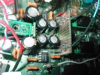
I just modded a CD1020, which is a repackaged CD43, but without the part of the PCB with the HDAM modules (instead there is a CMOS output switch...).
Long story short (I will post the long story too, there was quite a lot to do), the output stage is now based on a passive filter behind the DAC followed by a buffer-diff->se converter. My constraint was to use the existing PCB so I could only do this with OPamps, 3 per channel.
Keeping in mind that the machine started as a basic CD43, with all the mods the improvement in sound is nothing short of staggering.
mm2 said:
a passive low pass filter behind the DAC
and HDAM with v=5 ?
ilimzn said:
Long story short (I will post the long story too, there was quite a lot to do), the output stage is now based on a passive filter behind the DAC followed by a buffer-diff->se converter. My constraint was to use the existing PCB so I could only do this with OPamps, 3 per channel.
Keeping in mind that the machine started as a basic CD43, with all the mods the improvement in sound is nothing short of staggering.
Hi
This is starting to be very interesting....
Would you please explain the basics regarding "a passive filter behind the DAC"
Regards
Ricardo
RCruz said:
Hi
This is starting to be very interesting....
Would you please explain the basics regarding "a passive filter behind the DAC"
Regards
Ricardo
The NPC DAC used in the CD 43/53/63/1010/1020 family is a slightly odd beast regarding it's requirements for a filter, but some of this is applicable to other DACs as well.
Basically, the NPC DAC output is a 13-position PWM signal running at Fs*32, which is a fairly low frequency regarding filter design, but still high enough that careful attention has to be given to the OPamp used if the filter is active.
The problem with the original circuit is that the impedance the + and - differential PWM outputs see, is different at audio frequencies, and one of them is also highly dependant on the OPamp's open loop gain characteristics. This is because in an attempt to save on one OPamp per channel, the first two filter stages and differential to single-ended conversion have been merged into a single circuit. As a result, filtering for the + input to the OPamp is 'passive', while for the - input it is passive for the first stage, and 'active' for the second. 'Active' because for this particular circuit, a capacitor that goes to ground, forming the second stage of the filter, for the + OPamp input, ends up in the feedback loop of the OPamp, for the - OPamp input.
The effectiveness of this cap in the feedback loop depends heavily on how much open loop gain the OPamp has available at the frequency of interest. In general, the open loop gain is frequency dependant and falls with the rise of frequency, whereas the effectiveness of the cap should rise with the rise of frequency - after all this should be a low-pass filter. To make matters worse, the actual impedance of the cap is in series with the output impedance of the OPamp, which may be highly nonlinear at high frequencies. If one further looks at the actual OPamps used in the original circuit, one has to wonder how much open loop gain there is available at over 1Mhz, and the answer is a most emphatical, not enough.
The fact that the + and - DAC outputs do not see the same impedance at audio frequencies (and beyond) also contributes to PWM output edge asymetry. Because of the particular 'pseudo-differential' way the NPC dac works, this can translate into a form of noise similar to jitter.
To correct this problem, the putput stage was re-designed so that both + and - outputs of the DAC are passively filtered by a 3-stage filter (so, third order). Then, they are buffered by a sufficiently fast OPamp (one for each differential side), the idea being that the fiter characteristics are not altered by OPamp open loop gain (or indeed most characteristics) and the OPamps get a signal to work with, that has the HF component dubstantially filtered out already. Finally, a third OPamp is used as a differential to single ended converter, which is also augumented to form a first order filter, so the total filter order is 4. The DAC outputs see completely balanced impedances, the actual Opamps see a signal with an already substantially attenuated HF component.
Now, because the NPC DAC runs at a fairly low output rate due to it's PWM outputs, the filter corner frequency has to be set fairly low. Also, the PCB layout leaves a lot to be desired - >1Mhz signals are routed very circumvently by windy tracks several cm long, which form substantial inductors in in series with the filter caps, reducing their effectiveness. In an attempt to ameliorate this problem, the first stage of the filter is deliberately tuned lower than normal, and it is made differentially (cap is between + and - outputs of the DAC), so that most of the RF energy stays within a small loop area near the DAC. However, this results in about 1.5dB attenuation of the signal at 20kHz. The original filter had similar constraints, an attempt was made to correct this with the second OPamp which is also set up as a filter, with a notch at 32*Fs, as is well documented in this thread, INCORRECTLY. In the redesign, the buffer stages after the passive 3rd order filter have a suitable configuration so that a slight correction in form of a shelving filter can be added easily. As a result, the compound response stays within +-0.15dB right to 20kHz.
The final tweak is the addition of current sinks to the OPamp outputs to set the OPamp into class A. I have made this defeatable by jumpers, because not all OPamps work well set this way. All OPamps are on zero-length sockets (turned pins that fit directly into the PCB so the length the signal has to travel remains unchanged), and several OPamps have been tried, with quite surprising results. Also, there is no DC servo, but luckily, the CD1020 has two pairs of output connectors, normally connected in parallel - after the mod, one set is DC coupled to the OPamp output, the other is AC coupled through a capacitor.
Of course, more modifications were done to the power supplies and ground routing, this only covers the changes to the analog output section. I will post the svhematic for the new analog section later today...
Schematics of the output stage...
OPamps are not labeled as they are socketed (duals are used due to the existing PCB design). Also local decoupling for OPamps is not shown (RC filter off of + and - 12V lines, R=10ohms, C=470uF in parallel with 0u22 foil, also there is a 2n2 non-inductive foil between + and - power pins of the OPamp, given the layout, without it say, an OPA204 will oscilate).
If you look carefully, you will notice that t he elements of the passive filters form a resistance close to 12.1k at LF, balancing the 12.1k in the feedback loop of the buffer/shelving filter OPamps. This solves 3 issues:
1) Balanced load on DAC PWM outputs (AOUT+ and AOUT-).
2) Feedback resistors are mandatory for the shelving network anyway
3) A bipolar input OPamp can be used without causing undue offset problems, even though it is not an ideal choice for the job.
The 100p + resistor (39k shown) in series, between the - inputs of the OPamps is a part of the shelving filter network designed to correct excessive response droop at 20kHz. The resistor can be varied between 33 and 47k for minute adjustments to the actual frequency response over about 5kHz. The range of adjustment is about +-0.3dB, with 33k the response drops monotonically and has about -0.3dB loss at 20kHz, while for higher values there is a slight peak at 8-11khz (up to 0.15dB when the resistor is 47k) before the response drops, but the loss at 20k i sless. With 39k, the peak and drop are about balanced at around 0.1-0.15dB depending on component tolerances. While not obvious, the character of the sound does change quite perceptibly by varying this resistor, and can be used to 'offset' the character you get with various OPamps.
The current sink formed out of a single FET, selected for 6mA Idss, forces the OPamp to work in class A into loads as low as 600 ohms (with some current to spare). It reduces the maximum voltage swing available from the OPamp but the 12V power supply insures that t here is ample reserve over the 2V RMS output for 0dB full scale digital output. The current sink has a jumper so it can be disabled for OPamps that do not like this sort of thing.
I dod not try any exotic OPamps here, more what i had in storage - the usual NE5532 by TI (Originals are NJM4560), LM833, AD712, OPA2604, OPA2132, LT1022, LT1057. Quite surprisingly, the most pleasing and balanced sound was obtained by using AD712 for the buffer/shelving filter, and LM833 with current sink enabled, for the output.
Attachments
- Home
- Source & Line
- Digital Source
- Marantz CD63 & CD67 mods list