6h5c said:Don't forget to remove the muting transistors!
I didn't really hear any improvement taking these out, and he did ask for the top 3! Taking those caps out tho - wow! The bass!
Re: Re: adapters
I managed to get two decoupling caps under the IC sockets. I use this setup only for testing. After I find a good SMD opamp combo I solder them on a single-to-dual SO8 adapter that goes into the player.
Ray.
SimontY said:
Interesting. The pic, which is good, makes me wonder about all the extra trace and pin path for the signal. Does this not make it of paramount importance to place psu caps on each op-amp?
cheers
I managed to get two decoupling caps under the IC sockets. I use this setup only for testing. After I find a good SMD opamp combo I solder them on a single-to-dual SO8 adapter that goes into the player.
Ray.
davidsrsb said:Both the CD63 and CD6000 families are let down by the single tracking layer plus ground plane aproach. Most of the chips and decoupling have very indirect 0V connections. A few well placed chip ceramics might have far more effect than all of these audiophile exotica being suggested.
Looking at the supplies around the smd chips, even their 0V connections are noisy and the +5V is worse. The master clock is obviously jittery and the 470R series termination resistors in the clock outputs to the DACs and servo is too large, turning the secondary clocks into 3V pk-pk triangle waves. A suitable ferrite bead could give a much cleaner clock.
I agree, the PCB is not optimum. The CD57/67 layout is better though. But the local decoupling is also very important, a few small caps make a big difference!
I use a lot of 100n PPS capacitors on the bottom of the PCB, to replace the original 47n ceramics, and to put in parallel with the swapped el-caps.
Ray.
Attachments
SimontY said:I wish I could solder like that!
It's not too difficult. Use an iron with a fine tip that's not too hot, and thin solder wire with low-flux core. Place the el-cap in the PCB and bend the wires. Place the PPS cap on the bottom and solder it, that's all!
Ray.
Attachments
1 - remove dc blocking caps and short the spaces with a piece of wire
2 - add an after market clock
3 - power the clock with dedicated power
4 - change the op-amps
Well technicaly that could be three
1 - remove dc blocking caps and short the spaces with a piece of wire
2 - add an after market clock and power the clock with dedicated power
3 - change the op-amps
I got the player for about $30 and it does skip a bit sometimes so I don't want to put a large amount of cash into it. The price of most clocks are more then I am willing to spend. Is there an affordable alternative? How about the kwak clock?
Could you tell me what opamp to get and how many I will need? I know that people here have different opinions on them but I couldn't tell a good one from a bad by specs.
DJNUBZ said:
Well technicaly that could be three
1 - remove dc blocking caps and short the spaces with a piece of wire
2 - add an after market clock and power the clock with dedicated power
3 - change the op-amps
I got the player for about $30 and it does skip a bit sometimes so I don't want to put a large amount of cash into it. The price of most clocks are more then I am willing to spend. Is there an affordable alternative? How about the kwak clock?
Could you tell me what opamp to get and how many I will need? I know that people here have different opinions on them but I couldn't tell a good one from a bad by specs.
Hi,
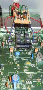
As an alternative the Kwak-clock is very easy to build. You can also use the single-supply version. Or you can use a Tent labs XO oscillator module, also works very well, with even less parts count. In the picture you see a small PCB I made, with a Kwak-clock oscillator and buffer, and a two-stage PSU. But you can also use vero-board.
As for the opamps, if you go for dual ones I can recommend the AD8620, you will need one for each channel. That will give you a lot of improvement compared to the original JRC2114.
To cure the skipping problem you can try cleaning the pickup lens, with a bit of isopropanol and a cotton-tip. If the lens is clean or it doesn't help, you can try and increase the laser-current a bit. There's a small adjustable trimmer on the flexfoil of the laser-unit. If you carefully turn it a few degrees clockwise that may help.
Regards,
Ray.
Attachments
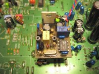
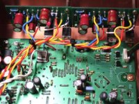
More caps exposed..
Next to the dac is a tent clock, right on the pcb. PS comes from an alw reg which also feeds the +5 clock ps on the dac.
Second alw reg for the +5 analog ps on the dac. Both have are fed by a 317 ps with own transformer.
Rest of the mods is like mentioned here (opamps/mute/headphone/etc).
it's a 63ki
Attachments
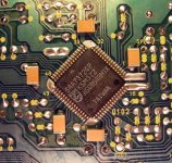
SimontY said:Ahha, I see the 'trick' to it now, very sharp pic, thanks. I've never even attempted to solder SMD, but as I get better I may try some caps. My DIL op-amp sockets are just looked after by 47uF Pany FC under the pcb.
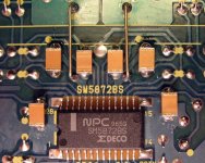
Here's the decoder part. I also use SMD resistors in the analog filter. They are small 0,1% MELF type. They fit exactly between two pads and are far less expensive.
Regards,
Ray.
Attachments
guido said:More caps exposed..
Next to the dac is a tent clock, right on the pcb. PS comes from an alw reg which also feeds the +5 clock ps on the dac.
Second alw reg for the +5 analog ps on the dac. Both have are fed by a 317 ps with own transformer.
Rest of the mods is like mentioned here (opamps/mute/headphone/etc).
it's a 63ki
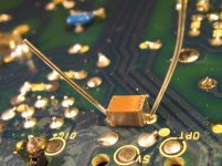
Hey, nice job Guido! Should do that too actually. More caps closer to the chip. What case size did you use? If it gets any smaller we'll need microscopes!
Ray.
6h5c said:
Hey, nice job Guido! Should do that too actually. More caps closer to the chip. What case size did you use? If it gets any smaller we'll need microscopes!
Ray.
Umm, small

Cant remember, but if you look at the pic and the distances between the legs of the dac, you should be able to determine the size.
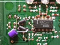
Did not do that much on the decoupling of the decoder/cpu etc. Just replaced the elco's with FC's and some smd caps iirc and swapped the ps diodes. Also those series restistors in the powerlines are replaced by inductors.
We should bring the the players to diy2006, can do a shoot-out
opamps are 6172
Attachments

guido said:
We should bring the the players to diy2006, can do a shoot-out
Yeah, I want to go there this year. When is it held?
Ray.

The Tent labs XO oscillator module looks like the right option for me because it is the simplest. Do I just replace the crystal with the piece or is there more I have to do? Would this be a simple job to do to upgrade most cd players? Would it work on a DVD player (ie. pioneer dv-578a)?
If putting the tent labs xo is as easy as it sounds I am going to do that, pull the DC blocking caps and upgrade the opamps. I havn't opened my player, are the opamps SMD? Is it just an R and R or is there more to putting them in?
If putting the tent labs xo is as easy as it sounds I am going to do that, pull the DC blocking caps and upgrade the opamps. I havn't opened my player, are the opamps SMD? Is it just an R and R or is there more to putting them in?
What you are saying is somewhat of an open book!!
BUT the Tent labs XO oscillator module is a complete clock so you need to remove the two ceramic caps that are attached to the crystal and the 1 meg ohm res that decouples them.
I assume the Tents lab instructions tell you to do this!!!
Yes remove the 4 DC blocking caps and bridge out
Yes the op amp are a major uprade in most cd/dvd players so do it.....(you need to let us know what is inside your dvd first though for proper advise on any thing other than cd 63/67 etc and open a different thred)
sorry if I dont sound helpful but im ****ed on good red wine and port lol
6h5c said:
Yeah, I want to go there this year. When is it held?
Ray.
www.dutchdiyaudio.nl 12 maart.
DJNUBZ said:I just want to make sure we are talking about the same thing. Rather then building or buying a whole clock unit I can buy the € 29 oscilator and just plug it in place of the crystal?
Yes that is basically it (you have to remove the caps and resistor too). HOWEVER it only improves things if you also use a very good powersupply to feed it. In my case an ALW reg with preregulation. Or indeed buy/build a clock with powersupply included, many flavours to choose from.
Browsing through the digital section (search) should give you plenty to read.
Opamps are DIP package ( and they are dual opamps) replacement is rather simple, but if you put in a fast opamp (like that 6172), the decoupling needs to be improved. Otherwise it might behave badly
My CD63 is now strictly modded by the Gerald Gessner style. This includes improving the power supplies for the DAC chip, changing ground layout and completely redesign of the output stage (just one OPA(2)134, passive filtering, no output caps).
One very interesting detail, I was not aware before: I inserted a Kwak Clock with the original quartz.
But the original Quartz is not precisely enough! It is a 16.935Mhz and not 16.9344! I does absolutely make no sense, to insert the original quartz into a Kwak, for this player!
Another very important hint you can find here:
http://www.acoustica.org.uk/t/63/63hacks.html
Franz
P.S.
Interesting detail: C522 and C523 are obsolete in any case, they don't exist in any service manual and should not be there!
Attachments
- Home
- Source & Line
- Digital Source
- Marantz CD63 & CD67 mods list