FAO brent
Ive tried to fit the 12v super-regs again today for my op-amps. I followed the list you gave me, but when i turned my player on there was no music, except for a crackle which was the main beat of the music :S
Ok i took out R613-616 and plonked the output of the +12v reg into the lower hole of r613. After measuring voltages, the reg is recieving 24v (form + pin of c803) to its input, and outputting 12V through r613, with the linked caps (linked +of c611 to + of c612) recieving 12V too.
But the -12V reg is recieving -24v (from - pin of c804) to its input, but when the output is soldered into R616 the output voltage is ~1V?
I tried hooking the output pin of this -12V reg directly to the pin of the BD adapter that it supplies, but still voltage stay at ~1v? (b.t.w - pins of c613 and 614 are linked).
But when i remove the -12v reg and just let it hang in mid air, i measure the voltage of the output pin and it reads the correct -12V voltage?
any ideas?
cheers
adfinni said:FAO brent
Ive tried to fit the 12v super-regs again today for my op-amps. I followed the list you gave me, but when i turned my player on there was no music, except for a crackle which was the main beat of the music :S
Ok i took out R613-616 and plonked the output of the +12v reg into the lower hole of r613. After measuring voltages, the reg is recieving 24v (form + pin of c803) to its input, and outputting 12V through r613, with the linked caps (linked +of c611 to + of c612) recieving 12V too.
But the -12V reg is recieving -24v (from - pin of c804) to its input, but when the output is soldered into R616 the output voltage is ~1V?
I tried hooking the output pin of this -12V reg directly to the pin of the BD adapter that it supplies, but still voltage stay at ~1v? (b.t.w - pins of c613 and 614 are linked).
But when i remove the -12v reg and just let it hang in mid air, i measure the voltage of the output pin and it reads the correct -12V voltage?
any ideas?
cheers
Everything sounds correct apart from one thing you have not mentioned and I think it could be your problem.
Looking at the front of reg reading pins left to right you have...
7812
Pin 1 = I/P
Pin 2 = Gnd
Pin 3 = O/P
7912
Pin 1 = I/P
Pin 2 = O/P
Pin 3 = Gnd
Did you wire up the 7912 correctly?
Brent
rowemeister said:
I found it helped bringing out the small details in the music and a little better channel seperation but I changed these at the same time as fitting 0.1% tol resistors.
I found changing silver mica caps all over helped alot especially with delicate treble.
Brent
I have easy access to 5% type silver mica's, will this be improvement over the ones that are in there now?
Ofcourse 1% will be better.
gy21 said:
I have easy access to 5% type silver mica's, will this be improvement over the ones that are in there now?
Ofcourse 1% will be better.
Yes these will improve the audio, if you have access try them mate. See what you think.
Also change the caps on the RF HF and Servo sections. You will get a much better treble and more low end bass
Brent
Yesterday I fitted my upgraded reg pcb and last night I had a listening session.
I can confirm my earlier findings with much clearer more natural vocals and a very tight crisp treble.
The fine details in background sounds are also more obvious.
Bass appears a little lower on double bass too.
I am very suprised by how much 'air' these Audiocom regs give to the music compared to my other pcb.
Brent
gy21 said:
I have easy access to 5% type silver mica's, will this be improvement over the ones that are in there now?
Ofcourse 1% will be better.
Capacitors are known for degradation of the (audio) signal to a certain degree. In my opinion silver mica is quite neutral, maybe because of the lack of coil forming like in the foil type. When very small signals are involved magnetism of the shoulders and leads may degrade the signal too.
When matching values above 10nF I use the DMM and a good quantity so equality better than 1% is not hard to obtain. For the smaller caps one needs a appropriate LCR. Maybe someone has a tip for matching these smal values?
Regards, Jaap
rowemeister said:
Yes these will improve the audio, if you have access try them mate. See what you think.
Also change the caps on the RF HF and Servo sections. You will get a much better treble and more low end bass
Brent
Thanks Brent,
One more question, the rf hf and servo caps, wich ones are that?
gy21 said:
Thanks Brent,
One more question, the rf hf and servo caps, wich ones are that?
There are loads mate.
The RF pcb is the one under your mech , then there is the HF circuit after it and then the caps near to servo.
Basically I changed all the caps on the RF pcb and all the caps in HF amp (before servo) and a few on the input of servo. You must use same value caps other wise you run the risk of it working very well.
Have a look at my mods list and look under 'Servo HF RF' section
")
Brent
rowemeister said:
Everything sounds correct apart from one thing you have not mentioned and I think it could be your problem.
Looking at the front of reg reading pins left to right you have...
7812
Pin 1 = I/P
Pin 2 = Gnd
Pin 3 = O/P
7912
Pin 1 = I/P
Pin 2 = O/P
Pin 3 = Gnd
Did you wire up the 7912 correctly?
Brent
yep 7812 is all ok, but the 7912 has pin 3 as the output surely
The 7912 is pin1 = gnd, pin2 = input, pin 3 =output. THat's what it says on the bottom of the reg (from left to right, G, I, O), or has it been labelled up wrong ?cheers
ad
p.s the forum was down for my last night
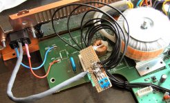
SimontY said:Morning all,
Here's a pic of my star earthing point. I used a double run of the wire to attach it to the IEC socket. The hole for the IEC was a nightmare to cut with a rubbish jigsaw..
Simon
Nice job on the IEC Simon.
Don't you espect these long earth wires near the torroid are apt for coupling?

Regards, Jaap
adfinni said:
yep 7812 is all ok, but the 7912 has pin 3 as the output surely
cheers
ad
p.s the forum was down for my last night
errr

me bad!!!

Yes you are right pin 1= gnd pin 2= i/p pin 3= o/p
I got it wrong sorry LOL
Brent
SimontY said:Morning all,
Here's a pic of my star earthing point. I used a double run of the wire to attach it to the IEC socket. The hole for the IEC was a nightmare to cut with a rubbish jigsaw..
Simon
Hi.
So I wasn't the only one with problems accessing the forum last night !
Cutting a hole for the mains connector is a pig. I was fortunate enough to find a square sheet metal punch [hole cutter] on a boot sale for 50p. It's not the correct size so I still have to file about 2mm from one side but it does save a lot of time and effort. It is possible to buy the correct size cutter for an IEC socket but the price makes it uneconomic for a one off [about £70]
If anyone is planning on cutting the hole for the socket, a round 3/4 inch cutter will save time and costs about £8
Andy
SimontY said:Morning all,
Here's a pic of my star earthing point. I used a double run of the wire to attach it to the IEC socket. The hole for the IEC was a nightmare to cut with a rubbish jigsaw..
Simon
Nice one Simon
Hope you are enjoing the benefits from this star earth
Brent
rowemeister said:
errr
me bad!!!
Yes you are right pin 1= gnd pin 2= i/p pin 3= o/p
I got it wrong sorry LOL
Brent
Damn i was hoping you were right
Had another look, and the +12v reg is outputting 12V fine, across the caps c611/612, leading to a BD.
But the -12V reg still gives out -1V (or 1v, can't remember which)when it is soldered into the hole of R616, and then gives out -12V when i touch teh output with y multimeter when it is hanging around in mid air

adfinni said:
Damn i was hoping you were right
Had another look, and the +12v reg is outputting 12V fine, across the caps c611/612, leading to a BD.
But the -12V reg still gives out -1V (or 1v, can't remember which)when it is soldered into the hole of R616, and then gives out -12V when i touch teh output with y multimeter when it is hanging around in mid air
Wire up the original 7912 and see what that does just incase the reg pcb is faulty.
Brent
rowemeister said:
There are loads mate.
The RF pcb is the one under your mech , then there is the HF circuit after it and then the caps near to servo.
Basically I changed all the caps on the RF pcb and all the caps in HF amp (before servo) and a few on the input of servo. You must use same value caps other wise you run the risk of it working very well.
Have a look at my mods list and look under 'Servo HF RF' section
Brent
Thanks Brent finally a good place to put my silmic 220uF ;-)
You left C126 on servo untouched, any reason for that? Some mods say to raise that value.
gy21 said:
Thanks Brent finally a good place to put my silmic 220uF ;-)
You left C126 on servo untouched, any reason for that? Some mods say to raise that value.
I may have gone blind...
I cant see C126
Brent
- Home
- Source & Line
- Digital Source
- Marantz CD63 & CD67 mods list