Another good night last night. I built a nice little off-board supply for my DOS with good quality parts. I have a PCB for the latest Jung/Didden SuperRegulator on the way, which I'm going to try building a +/-12v version of.
I have two issues that I want to debug:
- My right channel is very slightly quieter than my left. Also, the LED on the right side of the DOS always goes out slightly faster. All passive components are matched or closest available tolerance. All soldered joints seem good. Could be the 7912/7812 regs?
- The low level residual noise on the right channel in stop mode is noticeably louder. Both channels are a little 'roary' with the volume up, but the right channel has a sort of electronic drone to it. I'm feeding both DAC channels off the same 5v supply to debug. Could also be regulators? They're running on +/- 25v with heatsinks, which may be a little on the high side. I also wondered if the right channel could be picking up noise from the Flea?
The loudness difference could be caused by small differences in transistor Hfe or resistor tolerances. You say you matched all the components, did you match the parts per channel, or also between channels? Another cause could be the amp's volume control pot. Most stereo pots are not known for their good tracking between both channels. If you want to find out where the problem lies, you should measure the output amplitude of the player with a test CD.
Differences in noise level can be caused by differences between the filter parts. If a cap or resistor is not properly fitted, noise attenuation will suffer. It could be that both problems are related to one fault. Differences between filters will also mean slightly different signal output. It's not normal the LED behaves differently. This could indicate a wrong current setting in one channel. This will affect the working point of the transistors, and with that the amplification factor.
Hope this helps")
Differences in noise level can be caused by differences between the filter parts. If a cap or resistor is not properly fitted, noise attenuation will suffer. It could be that both problems are related to one fault. Differences between filters will also mean slightly different signal output. It's not normal the LED behaves differently. This could indicate a wrong current setting in one channel. This will affect the working point of the transistors, and with that the amplification factor.
Hope this helps
Thanks Ray. Great advice as always. I'll double check all solder joints. I'm certain that the problem lies in either the DAC, DOS, or some connection between because:
- The stereo image is perfectly centred for other sources
- If I reverse the L/R RCA cables to the amp, the channel difference swaps with it
The stereo image from the DOS was originally superb. Something has changed to affect it recently (after fiddling!), so I figure it must be a bad connection or some part is failing.
Incidentally, the green LED on one of my Fleas failed one day, sending the voltage to the XO oscillator skyrocketing. Thank goodness it failed visibly and I was around to see it! No problems with the replacement.
Last edited:
Agree, it must be located in the player then. Could it be that one of the DAC's outputs has come loose? Signal will still be there through the other input, but the amplitude will be less. Also, noise reduction may suffer because the two signals are no longer summed.
Thanks for reporting the broken LED. You're the first (which is a good thing of course...) but i'll keep an eye on it.
Ray
Thanks for reporting the broken LED. You're the first (which is a good thing of course...) but i'll keep an eye on it.
Ray
OK, I get the safety issue. That rules it out for sure. In terms of current, the notes said 80mA max, and from memory I think the highest current drawn from a 5v pin in the CD63 is around 30mA for the DAC digital.
Maybe...........
So why have you gone to all the trouble of fast high current capable psu's?
Simples, they sound better in most cases. I can only suggest that there are uSecond demands for direction changes on that require fast response and higher current.
Right Ian. My passing interest in the concept of a transformerless supply was borne out of the frustration of trying to cram multiple small toroids into an already cramped case.
So, following your line of thinking above, might a single large, high VA transformer potentially sound better than multiple small ones when feeding multiple low-noise, high current regulators?
Regarding my channel imbalance, the 7x12 regs on my DOS board measured 11.7v, -11.7v, 12v and 'BANG!'.
(The 'BANG!' was my shaky multimeter probe accidentally shorting out the -25v rail!)
Anyway, I think ~2.5% difference satisfactorily explains the tiny time delay between the LEDs going out. Whether that's the fault of the regs or a difference in the load they're supplying remains to be seen.
Regardless, I think I figured out the main cause of the noticeable channel imbalance. It turned out the grounding of RCA had come a bit loose. I have those copper CMC ones, and it's hard to get the solder to stick to them. I need to do more listening tonight to make sure.
CD63 new layout
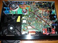
Last week I offered to tidy up one of my friend's CD63 that I had modded for him with budgeted components (this CD63 was the 1st mod I had made so the layout was not that good).
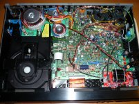
The first photo shows the initial layout while the 2nd one is the layout after I have made some adjustment to it. I also took the opportunity to change some of the caps for my friend. The SQ is smoother than before and my friend is really happy with it .
Last week I offered to tidy up one of my friend's CD63 that I had modded for him with budgeted components (this CD63 was the 1st mod I had made so the layout was not that good
).The first photo shows the initial layout while the 2nd one is the layout after I have made some adjustment to it. I also took the opportunity to change some of the caps for my friend. The SQ is smoother than before
and my friend is really happy with it .Attachments
The HA opamps do run hotter and I've thought about using heatsinks to cool them a bit. Can't see it changing the sound though.
Looking at the player, you've done a fair bit of psu work but nothing in the output stage other than opamps. Change the orange drops to polystyrene and run the Bessel filter. Its worth doing
*my bad! I can see you worked in that area in the 2nd picture
Looking at the player, you've done a fair bit of psu work but nothing in the output stage other than opamps. Change the orange drops to polystyrene and run the Bessel filter. Its worth doing
*my bad! I can see you worked in that area in the 2nd picture
Last edited:
The HA opamps do run hotter and I've thought about using heatsinks to cool them a bit. Can't see it changing the sound though.
Looking at the player, you've done a fair bit of psu work but nothing in the output stage other than opamps. Change the orange drops to polystyrene and run the Bessel filter. Its worth doing
*my bad! I can see you worked in that area in the 2nd picture
Yes you do have good eye sight. I did not do much as my friend has limited budgets
. All the caps are my spare components.Actually the opamps do not run hot they are about 50 C after long time running. As you said putting heat sinks on will not improve SQ but my friend requested me to put them on for peace of mind. They are my spare heat sinks.
I told my friend he could sell this CD63 and I will mod a better one for him using better components if he got more budget
Higlander, I notice you have heat sinks on your opamps. Do these make a difference to SQ? Also where do you get them from? Many thanks.
I did not notice any improvement in SQ at all with heat sinks on but my friend requested me to put them on for peace of mind. They do not run very hot, just about 50-55 C without heat sinks.
I bought a few fairs from eBay supplied outside UK (I think from Hong Kong) but they are hard to find
Hi gang,
First off - nice work as usual, higlander. I really like the way you mount your transformers on boards.
I'm still looking at this channel imbalance. I found that my DC offset of my DOS is equal with no power to the DAC at 6.6v per channel. With power to the DAC but no disc playing, the DC offset in the right channel drops to ~3.5v. All four DAC regs are steady at 5.25v. I'm starting to wonder if the DAC chip itself might be on the way out. I suppose the other possibility is a problem with the DAC analogue local decoupling caps? I might try swapping those next.
Any other ideas appreciated.
Cheers,
Ben
Also, I just confirmed that the DOS works fine with no significant noise in either channel when there is no power to the DAC. In that case, the LEDs power down simultaneously and all regs read the same current of 11.8v. It appears that the input from the DAC in the right channel alone appears to be causing the difference in current draw and DC offset.
I will double check again tonight, but all connections seemed good.
The noise in the right channel seems to have a 60Hz mains component to it, which is only present when the DAC is powered up. Could I have created a ground loop that only affects the right channel of the DAC?
The DOS is connected to the DAC with six wires total: Positive/negative outputs and an analogue ground per channel. The 6 DAC pins, including the analogue grounds, are no longer connected to the original PCB tracks; only to the DOS. Both DOS channels are grounded to the PSU 0v, which is in turn tied to the PCB's main star point.
Should the analogue grounds to the DAC still be connected to the PCB?
(PS I wrote 'current' above where I meant voltage. Ihavenoideawhatiamdoing.jpg)
Last edited:
Low Jitter clocks comparison
I just wanted to share my personal experience on the performance of low jitter clocks for those who wanted to choose a good clock for their CD63.
I have used the following low jitter clocks in eight of my CD63s:
1. Fidelity Audio's C3 clock
2. Fidelity Audio's C2 clock
3. Ray's Flea
4. Audio GD's low jitter clock (TCXO version)
(ºÍ§Ó*µ响)
5. Ultra low noise precision clock made in Korea
(R-Clock:High Precision Low Jitter Reference Clock with Ultra Low Noise Regulator | eBay)
6. Cheap Low jitter clock made in Taiwan.
From my experience the best performed clock is FA's C3 clock and the worst is the clock made in Taiwan (but it is really cheap). My preference are shown in the following order:
FA's C3
Low jitter clock from Korea
FA's C2 and Ray's Flea (they performed neck to neck)
Audio GD clock
Clock made in Taiwan.
Taking into account of the overall performance and price I would say Ray's flea is value for the money product.
BUT if you really want to make your CD63 perform at it best I would strongly recommend FA's C3 clock (but don't forget to ensure you have very low noise power supply to it)
I have also found that there is big improvement in overall SQ when using two separate clocks for the servo and the DAC instead of deploying frequency divider using a single clock for two frequencies.
As a matter of fact the CD63 KI SI that I owned used FA's C3 (with FA's CLK-R Clock filter) for the servo clock and a Korea made clock for the DAC. My CD63 out performed the other CD63s that I had made for my friends using the other clocks as mentioned above
I just wanted to share my personal experience on the performance of low jitter clocks for those who wanted to choose a good clock for their CD63.
I have used the following low jitter clocks in eight of my CD63s:
1. Fidelity Audio's C3 clock
2. Fidelity Audio's C2 clock
3. Ray's Flea
4. Audio GD's low jitter clock (TCXO version)
(ºÍ§Ó*µ响)
5. Ultra low noise precision clock made in Korea
(R-Clock:High Precision Low Jitter Reference Clock with Ultra Low Noise Regulator | eBay)
6. Cheap Low jitter clock made in Taiwan.
From my experience the best performed clock is FA's C3 clock and the worst is the clock made in Taiwan (but it is really cheap). My preference are shown in the following order:
FA's C3
Low jitter clock from Korea
FA's C2 and Ray's Flea (they performed neck to neck)
Audio GD clock
Clock made in Taiwan.
Taking into account of the overall performance and price I would say Ray's flea is value for the money product.
BUT if you really want to make your CD63 perform at it best I would strongly recommend FA's C3 clock (but don't forget to ensure you have very low noise power supply to it
)I have also found that there is big improvement in overall SQ when using two separate clocks for the servo and the DAC instead of deploying frequency divider using a single clock for two frequencies.
As a matter of fact the CD63 KI SI that I owned used FA's C3 (with FA's CLK-R Clock filter) for the servo clock and a Korea made clock for the DAC. My CD63 out performed the other CD63s that I had made for my friends using the other clocks as mentioned above
Attachments
Last edited:
Interesting, thanksI just wanted to share my personal experience on the performance of low jitter clocks for those who wanted to choose a good clock for their CD63.
Could you explain how you measured the relative performance? Was there some test equipment involved or just listening tests? Also, might be worth mentioning which of those clocks include built in divider circuits so they can natively clock the DAC and servo with just 1 unit.
Thanks,
James
- Home
- Source & Line
- Digital Source
- Marantz CD63 & CD67 mods list