Well, you're right... 18W at start to 16.2 normal work... Not bad just for 16Bit DAC )
I just cut traces to transformers because there are no traces in the middle layer to them.
p.s. I still don't understand my feelings from this DAC... I got truncate(ok or dither) to 16 bit and then 8x oversampling with 18bit playback )))
I just cut traces to transformers because there are no traces in the middle layer to them.
p.s. I still don't understand my feelings from this DAC... I got truncate(ok or dither) to 16 bit and then 8x oversampling with 18bit playback )))
about SM 5813 APT
... looking at the datasheet of this filter , the input format seems to be I2S ( regarding to the delay between Data and SCK ) , But the word I2s is'nt ever pronounced along the datasheet . Or am I wrong ?
Do you think I could feed this filter with an Amanero without modifications ?
Thanks in advance .
Hi guys!
The subject device playing for me like a standalone DAC with the Volumio (Raspberry Pi) transport.
I take DATA, BCLK and LRCK from GPIO pins of RPi, connect them to "chinese" AK4137 board and take full I2S signal from it.
The board (AK4137) configured for I2S input and RJ 16 bit 44.1 kHz output.
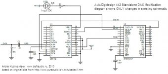
The full I2S signal "feeding" SM5813, that configured like on the picture (right chip), !!! but one mod: connect CKDV (3 pin) to the ground (you must cut the pin from pcb).
If anybody interesting, I can unswer the questions.
The subject device playing for me like a standalone DAC with the Volumio (Raspberry Pi) transport.
I take DATA, BCLK and LRCK from GPIO pins of RPi, connect them to "chinese" AK4137 board and take full I2S signal from it.
The board (AK4137) configured for I2S input and RJ 16 bit 44.1 kHz output.
The full I2S signal "feeding" SM5813, that configured like on the picture (right chip), !!! but one mod: connect CKDV (3 pin) to the ground (you must cut the pin from pcb).
If anybody interesting, I can unswer the questions.
Attachments
Hi!
It's another way:
You have four chips near the 50-pin connector, they are in the sockets (u28, u29, u32, u33).
Take them off - they have own cost and you can sell them))
First of all U32:
1. Connect pin 13 to pin 8 (you say the system that the input is digital - you will see it on the face of the device)
2. Connect pin 11 to pin 8 of any other chips (u28, u29, u33) - you say, that want to use "spdif" (not "AES / BU) - control it on the face
3. If you planing to use 48kHz input, connect pin 3 to any pin 8 (u28, u29, u33), if 44.1 kHz don't do it (you can control it on the face).
Second - U28 / U29:
1. Connect pin 1 of u28 to pin 3 of u29
2. Connect pin 7 of u28 to pin 5 of u29
3. Connect pin 9 of u28 to pin 11 of u29
Third:
1. Take away the U47 chip (24-pin chip with a white sticker)
2. Take a very thin wire (0.2-0.3 mm) and put this wire between the pin 2 and pin 18 - you must be cearfull because after it you must put the chip (U47) on it "s place. The wire must be thin, because it must be placed in the socket hole togather with chip pin. You can also use the welder to connect this two pins on the chip.
Hi!
It's another way:
You have four chips near the 50-pin connector, they are in the sockets (u28, u29, u32, u33).
Take them off - they have own cost and you can sell them))
First of all U32:
1. Connect pin 13 to pin 8 (you say the system that the input is digital - you will see it on the face of the device)
2. Connect pin 11 to pin 8 of any other chips (u28, u29, u33) - you say, that want to use "spdif" (not "AES / BU) - control it on the face
3. If you planing to use 48kHz input, connect pin 3 to any pin 8 (u28, u29, u33), if 44.1 kHz don't do it (you can control it on the face).
Second - U28 / U29:
1. Connect pin 1 of u28 to pin 3 of u29
2. Connect pin 7 of u28 to pin 5 of u29
3. Connect pin 9 of u28 to pin 11 of u29
Third:
1. Take away the U47 chip (24-pin chip with a white sticker)
2. Take a very thin wire (0.2-0.3 mm) and put this wire between the pin 2 and pin 18 - you must be cearfull because after it you must put the chip (U47) on it "s place. The wire must be thin, because it must be placed in the socket hole togather with chip pin. You can also use the welder to connect this two pins on the chip.
Hi
allev
I modified my 442 your way and it works but not well.
The audio signal appears at the AD1860 output (pin 9), but it disappears after a few seconds.
Can you give a hint or maybe you have a schematic of this 442?