Does anyone remember using or setting up a 442 ? The last time I saw one working was in the mid 90's, so I don't remember exactly what it did. From what I can work out so far, it seems, with the exception of the trimpots and maybe the meters, the front panel is dedicated to the '2' bit and 2ch digital I/O with the '44' bit providing simple 4ch analogue I/O. Not sure what the SSM2402 switches or the 4 relays do either. Its an easy enough job to carve it up and make it work but I'd rather not.
Well, some ideas I've had for the 442:
1) ignore the digital bits, and just use it as a simple mixer - two stereo inputs (DJ mixer and live act), two stereo outputs (sound system and recorder).
2) Add some S/PDIF receiver and transmitter chips, and use it as an outboard ADC/DAC for a computer sound card. Or, omit the S/PDIF stuff if the sound card has I2S I/O and the ADC/DAC stuff in the 442 can be persuaded to accept that.
3) Wire all the LEDs up to a CD4060 counter chip so they flash at various rates, and put some cryptic labels on it.
Putting these things together is a bit like Lego or Meccano. With enough knowledge and an ability to decipher datasheets, you can interconnect anything.
The SM5813 expects 16bit LSB justified data valid on the rising edge of bitclock (SCLK on the CS8412, Pin 12 and BCKI on the SM5813, Pin2). In order to use the embedded SPDIF clock, bitclock and L/R clock (FSYNC on the CS8412, Pin11 and LRCI on the SM5813, Pin28) have to be configured as outputs. This equates to mode 5 of the CS8412. To configure this mode the mode pins have to set as follows,
Pin 17 M3 = 0
Pin 18 M2 = 1
Pin 24 M1 = 0
Pin 23 M0 = 1
The SM5813 also requires a master or system clock on Pin 6 XTI.
With an external reference, system clock at 192/256/384/512Fs, bitclock at 64Fs and L/R clock at Fs would be generated. In this case all the clocks will be generated by the CS8412. The CS8412 only does 256Fs (MCLK Pin19), so this should be connected to XTI on the SM5813. To configure the SM5813 to accept system clock at 256Fs, /CKDV, Pin 4, has to be connected to V+ and /CKSL, Pin3 has to be connected to GND. You may also have to check /RST Pin 14. This may be connected to the computer port to allow an external reset. It can be connected to ground.
On the output side of the SM5813, the wordlength has to set to 18bits to match the AD1860. Connect /OW20, Pin 16 to V+ and /OW18, Pin17 to ground but they should already be set as should most of the output side settings. The connections to the dacs should need no alteration.
Did anybody make this? I did a try... All as in description and schematic. I cut traces and pins from original PCB. In addition to this I enabled SPDIF input - there is controlled buffer. As SPDIF source I used Creamware Pulsar (44.1KHz, ??bits). I tested it before on Logitech home audio with SPDIF input, works fine. But this mod doesn't... Can anybody point me idea why not? if my spdif is not 16bit - is it possible to use 24bit source with that schematic?
Another thing - I'm like a blind - I don't have oscilloscope.
Thanks in advance.
p.s. I'm not a fan of Digi, I just need additional outputs, quality doesn't matter.. and I have two units of 442 ))))
Andrei.
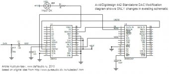
Well, I finished this project.
Here is final schematics based on rfbrw and TubeDac from pureaudio ideas.
Please, note, you'll find there ONLY changes. That means you must unsolder(or cut) pins from original PCB and wire to necessary points.
p.s. there is no spdif input transformer on this schematics. Later I added this by using existing T2 on board.
Good Luck!
Attachments
Fantastic work, I saw this thread years ago and have just come back for one last check in case anyone had got this working before I gave it away for someone else to use the case.
Now, I have a dismantled 442 and a soldering iron. There's a few things I'm not sure about, though...
I can see where to make new connections on your schematic, but I'm not sure how to work out where to cut existing PCB tracks. How do I deduce which connections to break?
There are 2 5813 chips on it - which of these should I use?
The S/PDIF input transformer - how important / worthwhile is doing this?
Apologies if any of this should be obvious to me - I've not done anything with digital electronics for about 16 years, and only did really basic stuff then.
dylofpoke ,
you can use any of 2 5813. First chip(that is closer to front) is responsible for 1 and 2 outputs.
if you see any wire to IC in my schematic then you must cut the pin from existing PCB. I mean cut IC pin in the point where it's soldered to PCB. NOT to cut PCB tracks. PCB is multilayer, sometimes it's impossible to find the track because it's in the middle.
Just be careful not to break pins of IC. but you have two 5813, you can damage one )))))))
About transformer - this is common to have it because it's ground isolation. But to be honest I didn't hear any difference for that type of DAC ))))))
Make it fist without transformer for the check. Adding transformer T2 is absolutely simple thing. You can use input circuit from this link
http://www.specialistauctions.com/auctiondetails.php?id=1217477
Andrei.
Thanks for the reply, I thought it might be that straightforward but I wasn't quite sure enough.
I've removed the socketed 8412 chip and bent the relevant pins upwards, but I'm not sure how to cut through the legs of the 5813 - I suppose I need some kind of long snippy tool. What did you use?
I've removed the socketed 8412 chip and bent the relevant pins upwards, but I'm not sure how to cut through the legs of the 5813 - I suppose I need some kind of long snippy tool. What did you use?
for 8412 I agree with, I made the same.Thanks for the reply, I thought it might be that straightforward but I wasn't quite sure enough.
I've removed the socketed 8412 chip and bent the relevant pins upwards, but I'm not sure how to cut through the legs of the 5813 - I suppose I need some kind of long snippy tool. What did you use?
5813 - I used knife(scalpel) to cut pins in the place of soldering to PCB.
Marvellous. Almost done! A few more questions about your schematic, though...
The schematic shows C1 and C2. I can't find these on the board - do they correspond to existing components or have you added them from elsewhere? The closest I can find is C3 and C4. They are labelled "103" - is this micro or picofarad? (I'm guessing pico) I may just buy them rather than removing them from the board.
R13 75R - is this 75 Ohm? Again, I think I'll just buy one rather than cutting R13 off the board.
+5VD - I've connected this to the post labelled "+5V" rather than "+5VA" - is this correct?
Thanks for your patience! With your help, I should hopefully be able to test this by Sunday and let you know whether it works.
Having looked at the schematic at http://www.pureaudio.idv.tw/images/tubedac-pcm63.pdf, I think I've answered my own questions - C1, C2 etc don't correspond to capacitors on the 442 board but to capacitors on the tubedac schematic instead. So I'll buy the parts (or find them in one of my many broken appliances or boxes of junk) and leave the bits on the 442 board alone.
Fantastic! It works!
Now, what else can I do with this? If I could have it converting 4 channels D>A, or even better, doing A>D conversion through the other S/PDIF at the same time...
Good!!! sorry I was not able to answer earlier.
What else? In my case I added second CS8412 chip and got two additional channels for Creamware(Sonic-core) Pulsar.
I decided to not spend a time for digging in A->D. Basicaly it's the same ADC that was in Turtle Beach Pinnacle ISA board. I don't like its sound... but it was cool board in the past...
I've connected the CS chip to both 5813s, so it outputs on all 4 XLRs, but if I could add another S/PDIF input, that would be cool. Is that what you've done? If so, how? Can the CS8412 take an extra input? If so, which pins should I use?
Thanks for all the help - I have an old M-Audio Duo USB on one computer which does ASIO but is really noisy, so it'll be useful to have a decent converter to put it through.
Thanks for all the help - I have an old M-Audio Duo USB on one computer which does ASIO but is really noisy, so it'll be useful to have a decent converter to put it through.
I've found that the 442 uses 17 Watts, whereas my TC M300 (which also works as a standalone D>A converter) only uses 5W. I suppose modern hardware is bound to be more energy efficient than 20 year old hardware.
I need to find a way to justify all those extra Watts, or remove some hungry redundant components from the 442.
I need to find a way to justify all those extra Watts, or remove some hungry redundant components from the 442.
Sorry, I should have read your post properly - a second CS8412 chip, good plan. They're cheap enough on Ebay. Did you just stack it on top of the first one?
I'm too used to posting in forums where I can edit my posts later to make it seem like I'm not a complete fool.
Don't worry )))
Well, I used separate scheme on small piece of bread board.
I just copied a part from this schematics and added second unused transformer
http://www.pureaudio.idv.tw/images/tubedac-pcm63.pdf
Did you find the label that 442 uses 17W or you messured that? I can check it if it's really big point for you. 17Wattsss.... Do you have Watt limit or you're trying to decrease monthly bills?
I measured 17W with a plug-in meter, just because I noticed how warm the 442 became when switched on. It's not specifically to save money, though obviously that's one good reason to save energy. I think the LEDs on the front of the 442 look cool enough to justify using it instead of the M300 ")
I've already seen that schematic. Putting the second CS8412 chip on a separate board seems like a good idea.
Transformers - how do you add these? Do you just connect one coil between the S/PDIF in's signal and ground and the other between the 442's ground and D-In? I guess you have to unsolder it first, as the legs don't seem to be visible above the circuit board.
- Home
- Source & Line
- Digital Source
- digidesign 442 I/O as standalone DAC for S/PDIF transport