Hi guys,
Got this chip out of a transport, called Merlin. Looks budget but no digital out. It literally only has this chip in line with output. They scratched the writing on front and on back I tried searching but couldn't find a proper part.
Any help appreciated. I can try get photos of the transport itself if required. Thanks
Attachments
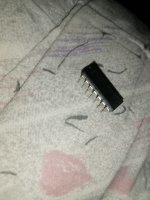
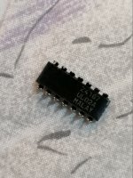
I had this sent earlier as I knew it might be needed. Its a 14 pin IC and seems to use pin 4 and 6 for the different outputs. The chip sits in U2
The 2 grey cables underneath I was told come from the cd mechanism which has a circuit board underneath. That seems to be the input (?) that then goes to pin 1 on the IC
So if I'm correct
pin 1 = Input (from cd mechanism)
pin 4= Coax output
pin 6= Some other digital output (funny connector never seen before)
pin 14= +5v supply
Thats it!
The H3 output is what I'm interested in. Thats the Coax.
Attachments
You could try using the oscilloscope and see what voltages/waveforms you get at 1,4, and 6. That will tell you exactly what the IC is / what it does... I suppose you have already done the "UL02A" search...?? => 2-input CMOS NOR gate
If the chip is faulty which I believe it is then there will no waveforms etc. Ul02A seems to be a 5 pin IC..
I'll take a wild guess - 74HC04 hex inverter.
Here's a testable prediction - if I'm correct, pin 2 and pin 3 on U2 will be connected together.
Pin2 and 3 are not connected to each other. Will 74HC04 still work?
(CAREFULLY) get the sockets off, so we can see the print properly, be very careful not to damage any print or via's
At the least get a better overhead photo with nothing in the way and then meter out which pins go where, we'll soon work out what logic it is.
You'll have to replace the sockets with new afterwards anyway as they won't be a fit state.
At the least get a better overhead photo with nothing in the way and then meter out which pins go where, we'll soon work out what logic it is.
You'll have to replace the sockets with new afterwards anyway as they won't be a fit state.
Thanks for help guys!!
This is the exact pin arrangements
pin 1 = Input (from cd mechanism)
pin 4= Coax output
pin 6= Some other digital output (funny connector never seen before)
pin 7 = Ground
pin 8 = Ground
pin 10 = Ground
pin 12 = Ground
pin 14= +5v supply
Are you going off what you can see on the underside , or taking into account tracks on the component side too ..........
PS:Show us the funny connector too
I did all tests yesterday.
The pin arrangement is 100% accurate.
The funny connector turned out to a optical connector and it says At&T on it but almost looks like BNC connector
Camelot techology merlin cd transport , Arthun dac & the dragon jitter SOLD
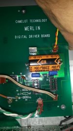
You can see the transport in this picture at the bottom (only picture I can find online) but doesn't show the connectors.
I can take some proper pictures tomorrow if needed.
The pin arrangement is 100% accurate.
The funny connector turned out to a optical connector and it says At&T on it but almost looks like BNC connector
Camelot techology merlin cd transport , Arthun dac & the dragon jitter SOLD
You can see the transport in this picture at the bottom (only picture I can find online) but doesn't show the connectors.
I can take some proper pictures tomorrow if needed.
Doesn't add up given what you've given
Have you gone down each adjacent pin looking for connections between each other?
It's gotta be a 74LS04 inverter (as a buffer) , but 2 and 3 would be connected together.
If this wasn't working beforehand I'd still recommend removing the sockets
Have you gone down each adjacent pin looking for connections between each other?
It's gotta be a 74LS04 inverter (as a buffer) , but 2 and 3 would be connected together.
If this wasn't working beforehand I'd still recommend removing the sockets

They are £2!! 74LS04
You sir are being robbed
You could also fit the schmitt trigger version 74LS14 as an upgrade
This is the exact pin arrangements
pin 1 = Input (from cd mechanism)
pin 4= Coax output
pin 6= Some other digital output (funny connector never seen before)
pin 7 = Ground
pin 8 = Ground
pin 10 = Ground
pin 12 = Ground
pin 14= +5v supply
The pins on the right side don't fit 74HC04 hypothesis. The inputs would be connected to GND and those are the odd numbered pins (9,11 & 13). Incidentally if its a 74LS04 the pinout is the same but then there's no reason to connect those unused inputs to GND. TTL is happy to have inputs floating.
Last edited:
- Home
- Source & Line
- Digital Source
- Please help identify chip