I'm starting a new project. I have 4 "Philips-based" vintage CD players to restore:
Proton AC-300II
Magnavox CDB480
Mission PCM4000
Magnavox CD2000

Three of them are currently able to play a CD. The 4th may become a parts donor.
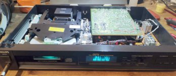
I'm really eager to restore this Mission PCM4000.

It contains the CDM-2 optical transport and a TDA1541 (no suffiix) DAC. The PC boards appear to have been manufactured by Philips. My example of this machine is dusty & dirty and it desperately needs a new tray drive belt. Otherwise it is fully functional. I'm looking forward to putting this one into my main 2-channel audio system after I finish cleaning/restoration.
The Proton AC-300II is also a CDM-2 and TDA1541 machine.

Closer view of the Proton's CDM-2 transport:

The Proton contains a TDA1541A DAC with an "R1" stamp.

It's only electronic problem is a non-functional 4-digit front panel display. This is a relatively common issue with Philips CD players. And though Proton used a different-looking 4-digit display module, it too failed. A clever diyAudio person researched this and made PC boards for a "new" exact replacement 4-digit display for Philips-based CD players. Details are here:
NSM4202A LED Display Module Replacement for Philips / Sony CDM Transports
I already have the PC boards and most of the parts to put on them. I'll also be checking/replacing electrolytics & solder connections, cleaning everything up, & testing it. It will be interesting to compare the sound of this Proton AC-300II to the Mission PCM4000.
The 2 Magnavox CD players are CDM-4 and TDA1543 machines.


One has a non-functional main PC board. It gets as far as weakly spinning the disc backwards about 4 turns before delivering "Err" on its display. The other machine has a CDM-4 with no measurable IR light output from its laser diode. I transplanted the good CDM-4 into the machine with a working PC board. Bingo! It's playing.
Standby for more!
-EB
Proton AC-300II
Magnavox CDB480
Mission PCM4000
Magnavox CD2000
Three of them are currently able to play a CD. The 4th may become a parts donor.
I'm really eager to restore this Mission PCM4000.
It contains the CDM-2 optical transport and a TDA1541 (no suffiix) DAC. The PC boards appear to have been manufactured by Philips. My example of this machine is dusty & dirty and it desperately needs a new tray drive belt. Otherwise it is fully functional. I'm looking forward to putting this one into my main 2-channel audio system after I finish cleaning/restoration.
The Proton AC-300II is also a CDM-2 and TDA1541 machine.
Closer view of the Proton's CDM-2 transport:
The Proton contains a TDA1541A DAC with an "R1" stamp.
It's only electronic problem is a non-functional 4-digit front panel display. This is a relatively common issue with Philips CD players. And though Proton used a different-looking 4-digit display module, it too failed. A clever diyAudio person researched this and made PC boards for a "new" exact replacement 4-digit display for Philips-based CD players. Details are here:
NSM4202A LED Display Module Replacement for Philips / Sony CDM Transports
I already have the PC boards and most of the parts to put on them. I'll also be checking/replacing electrolytics & solder connections, cleaning everything up, & testing it. It will be interesting to compare the sound of this Proton AC-300II to the Mission PCM4000.
The 2 Magnavox CD players are CDM-4 and TDA1543 machines.
One has a non-functional main PC board. It gets as far as weakly spinning the disc backwards about 4 turns before delivering "Err" on its display. The other machine has a CDM-4 with no measurable IR light output from its laser diode. I transplanted the good CDM-4 into the machine with a working PC board. Bingo! It's playing.
Standby for more!
-EB
Last edited:
Here is an example (Magnavox CDB480):Start by replacing the 33uF blue caps near the cdm. Replace with same value.

The blue axial-lead electrolytic in the middle of this photo is in the APC (automatic power control) circuit for the laser diode.
It is directly in front of the red label and to the right of the white plastic connector.
This one is marked 47u, 25V.
If this capacitor dries out then the machine will fail to initialize discs.
The original factory value was sometimes 33uF and sometimes 47uF.
It isn't always blue. But the blue ones are notorious for "drying out" and causing the player to fail to read discs.
Actually a very important part of troubleshooting and restoration for all audio gear >15 years of age is to check and replace electrolytic capacitors.
There are two measurements which matter: uF (capacitance), and ESR (equivalent series resistance).
Both should be checked before declaring that an old electrolytic capacitor is still good.
Some people prefer to replace all of the electrolytic capacitors.
Electrolytic capacitors don't cost very much.
Today's capacitors last longer than old ones.
If you are skilled at desoldering and soldering then this can be done pretty quickly.
I routinely replace most (if not all) of the electrolytic capacitors when I restore vintage audio gear.
-EB
I have a question for diyAudio members who have plenty of hands-on experience with Philips CDM-2 & CDM-4 CD players:
Philips service manuals describe a “service program” (or “service position”).
My understanding is this gets initiated by holding down 2 or 3 front panel buttons simultaneously just before switching on the mains power. Then the buttons are released after the power is on.
The service manual describes several “service program” modes: 0, 1, 2, & 3.
I think these are supposed to do the following things:
1: Switch on the laser diode
2: Perform focus search
3: Enter play mode
My issue is that none of my Philips CD players will enter this “service program.” I’ve tried just about every permutation of 2 or 3 front panel buttons held down while turning on the mains power switch.
What am I missing?
-EB
Service program works fine at least on my CD640 (CDM2/10) - there it's four buttons: Prev./Next/Program/OpenClose.
Didn't try on my 304 and couldn't find any info yet for my CD618/620/624/630 yet on how to enter it but I guess it would work with the correct button combination.
Didn't try on my 304 and couldn't find any info yet for my CD618/620/624/630 yet on how to enter it but I guess it would work with the correct button combination.
I’m making a list of the service manual instructions for which multiple buttons to hold down at power-up to initiate “service mode” (service program) for Philips CDM-2 and CDM-4 machines.
It certainly varies from one model to another!
[Track >] [Track <] [Stop]
[Track >] [Track <] [Time/Track]
[Track >] [Search >] [Time/Track]
[Track >] [Search >] [Lap/Remain]
[Track >] [Stop] [Pause]
[Search >] [Pause] [Repeat]
I also found one instruction to hold down only 2 buttons at power-up:
[Track >] [Play]
I’ll try these button combinations on my 4 CD players. If any of them work I’ll post the working button combinations.
If none of them work, then I’ll methodically work my way through every possible 3-button combination. [Track >] is used more often than any other button. So if I wind up doing this I’ll start with button combinations that have [Track >] for one of the buttons.
-EB
Success!
I can get the Mission PCM4000 to enter the "service program" by holding down the [Track >] [Track <] [Time] buttons and then powering up.
FYI the normal user display at power-up without a disc in the tray looks like this:

But when the "service program" starts up the entire display is dark except for the single digit "0."
The number "0" shows up immediately after power-up instead of the normal user display.

When there is a disc in the tray the "service program" advances from 0 > 1 > 2 > 3 each time the [Track >] button is pressed.


These "service program" modes behave as follows:
Next I'll determine how to initiate the "service program" on the 3 other Philips-based CD players which are part of this project.
-EB
I can get the Mission PCM4000 to enter the "service program" by holding down the [Track >] [Track <] [Time] buttons and then powering up.
FYI the normal user display at power-up without a disc in the tray looks like this:
But when the "service program" starts up the entire display is dark except for the single digit "0."
The number "0" shows up immediately after power-up instead of the normal user display.
When there is a disc in the tray the "service program" advances from 0 > 1 > 2 > 3 each time the [Track >] button is pressed.
These "service program" modes behave as follows:
- 0 - Idle
- 1 - Focus search:
- If there is no disc in the tray the lens moves up and down 16 times.
- The laser diode is on during the focus search.
- When there is no disc the display remains at "0."
- When there is a disc and the focus search is successful, then the display advances to "1" - 2 - The spindle motor begins to rotate
- 3 - The disc begins to play
Next I'll determine how to initiate the "service program" on the 3 other Philips-based CD players which are part of this project.
-EB
CDM2 players also have a 33uF (or 47uF) electrolytic in their laser APC (automatic power control) circuit.Both the CDM4 players could be the same fault.
Start by replacing the 33uF blue caps near the cdm. Replace with same value.
For CDM2 machines this capacitor is located on the small servo circuit board attached underneath the CD transport mechanism.
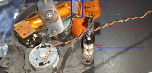
Today I inspected the transport from my Mission PCM4000.
It has the "blue axial lead 33uF electrolytic capacitor" which often fails.
In this photo it is located just above the TDA5708P IC:

This old 33uF capacitor had nearly 9 ohms of ESR (equivalent series resistance).
This is a sign the capacitor is drying out and will eventually fail into an "open circuit" condition.
This CD player was still working OK but I'm sure it would eventually fail if the old capacitor was left in place on the PC board.
I replaced it with a 47uF capacitor which has less than 1 ohm of ESR.
Caution: This PC board has no labels indicating capacitor polarity.
Be sure to observe correct polarity when replacing electrolytics.
I had a photo of the original capacitor before I removed it.
I can't overstress how important it is to take photos of everything before disassembling and before removing components from a PC board.

I routinely use radial lead capacitors (as shown in this photo of the replacement capacitor installed on the PC board) because radial lead capacitors are available in many more varieties.
There's no good reason why this capacitor would need to have axial leads.
The ESR of the 4 other electrolytics on this PC board tested perfect.
I didn't feel any strong urge to change them.
But that blue 33uF capacitor was definitely "on the way out" with 9 ohms of ESR.
-EB
Those different variations will be good to see.Also, different factory mods (and I've seen a lot) to the CDM2 servo board are of interest. I'll share pictures of my two boards soon.
I really don’t know how much the Mission PCM4000 I’m working on right now differs from the Philips model it is based on. The only section that looks really “non-Philips” is the front panel display and it’s associated PC board. Mission uses a rather elaborate VFD display. I don’t recall anything like that on Philips machines.
-EB
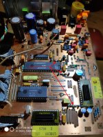
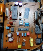
First in the row: Philips CD640 from 1986
Basically working, but had troubles with CD-Rs.
Complete overhaul, replaced every electrolytic cap - where possible with tantal or Philips SAL (orange drops, solid aluminium, 125° rated). Mostly capacity is lower then original, therefore I had to lower the R in the RC filters to maintain roughly the same RC-frequency.
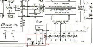
SAA7220P/A => SAA7220P/B from '92
TDA1541 => TDA1541A
no sockets, both with underlying heat-transfer tape and small heatsinks on top.
TDA1541:
DEM capacitors replaced with Panasonic PPS SMD caps, 100nF and Wima 470nF PET caps on the MSB.
"Grundig" Mod for the DEM (see attachement)
Power supply decoupling caps replaced with 100nf NP0/C0G
Analog output:
removed de-emphasis circuitry completely
replaced remaining caps with FKP2 where I had the right values.
replaced DC filter electrolytics with 6u8 MKS02, increased the following GND termination resistors from 4k7 to 37k to maintain low-frequency response.
Opamps in the analog output section exchanged to OPA1656, adapter PCB with heat-transfer glue directly to the PCB. No stand-off pins to reduce conductor length.
CDM2:
- optics cleaned on all reachable surfaces, focus unit taken off to do so.
- lubricated the spindle with homebrewn solution: 2/3 standard fine mechanic oil, 1/3 hexagonal bornitride (hBN)
- all other moving parts greased with "Gear-Flon", a German model making grease with PTFE
=> of course, given the efforts it sounds extremely good")
=> now ready every CD-R I throw at it with a extremely low failure rate, TOC will always be read, failures, when they happen, only at the outside of the CD and can be rectified by pressing play again.
Happy restoring!
Basically working, but had troubles with CD-Rs.
Complete overhaul, replaced every electrolytic cap - where possible with tantal or Philips SAL (orange drops, solid aluminium, 125° rated). Mostly capacity is lower then original, therefore I had to lower the R in the RC filters to maintain roughly the same RC-frequency.
SAA7220P/A => SAA7220P/B from '92
TDA1541 => TDA1541A
no sockets, both with underlying heat-transfer tape and small heatsinks on top.
TDA1541:
DEM capacitors replaced with Panasonic PPS SMD caps, 100nF and Wima 470nF PET caps on the MSB.
"Grundig" Mod for the DEM (see attachement)
Power supply decoupling caps replaced with 100nf NP0/C0G
Analog output:
removed de-emphasis circuitry completely
replaced remaining caps with FKP2 where I had the right values.
replaced DC filter electrolytics with 6u8 MKS02, increased the following GND termination resistors from 4k7 to 37k to maintain low-frequency response.
Opamps in the analog output section exchanged to OPA1656, adapter PCB with heat-transfer glue directly to the PCB. No stand-off pins to reduce conductor length.
CDM2:
- optics cleaned on all reachable surfaces, focus unit taken off to do so.
- lubricated the spindle with homebrewn solution: 2/3 standard fine mechanic oil, 1/3 hexagonal bornitride (hBN)
- all other moving parts greased with "Gear-Flon", a German model making grease with PTFE
=> of course, given the efforts it sounds extremely good
=> now ready every CD-R I throw at it with a extremely low failure rate, TOC will always be read, failures, when they happen, only at the outside of the CD and can be rectified by pressing play again.
Happy restoring!
Attachments
Last edited:
I’m only beginning to read through the huge threads of posts about mods for these Philips CD players.SAA7220P/A => SAA7220P/B from '92
TDA1541 => TDA1541A
no sockets, both with underlying heat-transfer tape and small heatsinks on top.
But if I’m understanding what I’ve read so far in regards to popular mods:
The versions of the SAA7220 and TDA1541 need to match:
- SAA7220P/A works with TDA1541
- SAA7220P/B works with TDA1541A
Some people bypass the SAA7220 entirely. This removes the “4x oversampling.” This mod is often referred to as “NOS” (non-oversampling).
Many improved clock circuits have been developed to replace the factory clock circuit.
The power supply rails for the SAA7220 need to be very stable and very well filtered because the SAA7220 generates a lot of noise on the power supply rails due to its digital nature.
Reviewing your modifications (please confirm if I’m correct):
Keep 4x oversampling
Upgrade capacitors & opamps
Remove de-emphasis
Upgrade capacitors & opamps
Remove de-emphasis
At this time I intend to get these 4 CD players into “fully functional” condition but I don’t plan to modify anything right away.
-EB
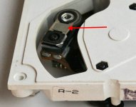
How difficult is it to dismount the focus/lens assembly for more thorough cleaning of the optics?CDM2:
- optics cleaned on all reachable surfaces, focus unit taken off to do so.
- lubricated the spindle with homebrewn solution: 2/3 standard fine mechanic oil, 1/3 hexagonal bornitride (hBN)
Regarding spindle motor lubrication, I am not very familiar with the brushless hall-effect spindle motor. This type of motor is in my Mission PCM4000. It is functional and rotates freely when turned by hand. Should I attempt to lubricate it or leave it “as-is?”
-EB
Hi,
I've never found the NON-OS to be particularly significant.... 7220P/A goes with TDA1541 non-A only. 7220P/B does sound nicely with 1541 non-A and A DACs equally well, I couldn't hear a major difference. I also own 7220P/Cs from digital satellite receivers, they sound more crisp with the standard Bessel filters as they where designed with a different analog filter in mind.
What I've planned with my device is to implement some extra supply regulators for the TDA1541 and the SAA7220 for the +5V line. But that is to some extend equalized by using the modified (L)RC filters I've already implemented. And I want my players to not look modified on the first glance, that permitts a complete optimized power supply (read, do not want to use any boutique regulators there).
I've got a dedicated clock in preparation, this then can be fed centrally to the SAA7220 and the SAA7210 (originally, the 7220 creates it and then feeds it to the 7210).
Lens cleaning is relatively easy if you have a steady hand, be prepared, there are counter-nuts (CDM4) or a counter plastic part with the corresponding windings (CDM2) under the assembly that fall out once the screw has been loose. Work on a clean surface so not to loose any parts. CDM2 is easier in that regard as the plastic part doesn't get lost that easy.
What I've learned recently, a well-lubricated spindle is eminent for the tracking to work well. The brushless motor from the CDM2 is a very simple and mostly fail-safe construction, compared to CDM0/CDM1.
=> therefore I strongly recommend to clean the spindle (I use car polish) and relubricate it with some high grade stuff (high viscosity oil, not grease)
Do not forget the counter part that presses on the CD from above to the drive - with CDM4 there is plenty of information (the ball leaves an indent after long usage, remove that by sanding it straight), the CDM2s I have do not have a ball there at all, just plastic on plastic - use a high grade grease there like the one I've recommended above with Teflon in it)
I've replaced the LM324 by an MC33079 on the spindle-drive sub board as well, not shure if that makes any difference as I've done it all along the other mods. But then, I've included an extra decoupling cap from VCC to VEE at the op-amp to cope with the extra bandwith the MC33079 has compared to the LM324.
Best, Markus
Edit - P.S.: do not underrate the "Grundig"-mod with the zener diode. I feel it cleanes up the sound stage and is much less complicated to implement than those mods including flip-flops.
Last edited:
extra notice:
the analog output opamps factory wise are supplied over ~100Ohm to ~100uF.
I've replaced that by 10Ohms to 3u3F Philips SAL (10uF tantals might be a good alternative).
The OPA1656 I've used (and that applies to most modern op-amps) have much better PSRR, therfore its less important to decouple the lower frequencies well, but more importantly to represent them a lower impedance and better HF decoupling.
That can be done with low ESL caps like tantalum, SAL or other solid electrolytics (OS-CON).
ESL mostly is determined by the physical dimensions, in order to fit caps into the original holes some compromises have to be taken. A better solution would be to fit SMD tantalume on the bottom layer, but that leaves the top layer somewhat empty and I do not have all values available in my bin.
Important note: all capacitors except the electrolytics ones are high quality surplus ones.
Therefore I had to make some compromises regarding some of their capacitance values.
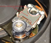
Another note: While cleaning the optics, make sure that extra plastic foil/film on the focus spring doesn't get lost (see picture attached).
This applies to CDM2 and CDM4 (and CDM0/1).
These plastic parts play an important role in keeping the mass-spring system correct. If those parts are lost, the servo control systems Q is to high resulting in mis-tracking.
At some drives, the original glue was apparently very weak, so please play attention to that. Personally, I've never had any problems with that.
Attachments
Last edited:
About a year ago I began ordering this brand of "standard" radial electrolytic capacitor from Digi-Key:extra notice:
the analog output opamps factory wise are supplied over ~100Ohm to ~100uF.
I've replaced that by 10Ohms to 3u3F Philips SAL (10uF tantals might be a good alternative).
The OPA1656 I've used (and that applies to most modern op-amps) have much better PSRR, therfore its less important to decouple the lower frequencies well, but more importantly to represent them a lower impedance and better HF decoupling.
That can be done with low ESL caps like tantalum, SAL or other solid electrolytics (OS-CON).
ESL mostly is determined by the physical dimensions, in order to fit caps into the original holes some compromises have to be taken. A better solution would be to fit SMD tantalume on the bottom layer, but that leaves the top layer somewhat empty and I do not have all values available in my bin.
Important note: all capacitors except the electrolytics ones are high quality surplus ones.
Therefore I had to make some compromises regarding some of their capacitance values.
Würth Elektronik
Blocked
Are you familiar with this brand?
They cost a bit more than Panasonic but often have lower ESR (and larger ripple-current ratings) compared to other brands of standard electrolytics. Digi-Key is a very large parts distributor in the USA. I've been ordering electronic parts from them for >35 years.
I agree that "solid electrolyte" capacitors have even lower ESR than standard electrolytic capacitors. And of course their main advantage is that they can handle incredibly high ripple currents. I tend to use them for repairs where a standard electrolytic had "vented" (where the can bulged out or exploded).
-EB
Thanks very much for those cleaning and lubrication tips!Hi,
Lens cleaning is relatively easy if you have a steady hand, be prepared, there are counter-nuts (CDM4) or a counter plastic part with the corresponding windings (CDM2) under the assembly that fall out once the screw has been loose. Work on a clean surface so not to loose any parts. CDM2 is easier in that regard as the plastic part doesn't get lost that easy.
What I've learned recently, a well-lubricated spindle is eminent for the tracking to work well. The brushless motor from the CDM2 is a very simple and mostly fail-safe construction, compared to CDM0/CDM1.
=> therefore I strongly recommend to clean the spindle (I use car polish) and relubricate it with some high grade stuff (high viscosity oil, not grease)
Do not forget the counter part that presses on the CD from above to the drive - with CDM4 there is plenty of information (the ball leaves an indent after long usage, remove that by sanding it straight), the CDM2s I have do not have a ball there at all, just plastic on plastic - use a high grade grease there like the one I've recommended above with Teflon in it)
-EB
"Würth" named capacitors are relatively new. They have a fancy appearance.
If you ask me, they just rely on the German name.
I would not use them, I only trust Japanese brands, and there only Panasonic, Rubycon, Nichicon and Nippon ("United" in the US) Chemi-Con. If I buy new electrolytics, I only take Panasonic FC, FM, FR. They have an unmatched track record for us hobbyists. The company I'm working for uses mostly Rubycon caps in the area >63volts and Nippon Chemicon <63volts. Our products are rated for 20yrs of usage (PV inverters).
I just recall Würth as a company that sells screws, nuts & bolts. Not a company that has a reputation in electronics, although they seem to have bought up some named companies in the inductor branch.
Btw - there is one french company, I do not recall the name, that I was told that produces the *best* electrolytic capcitors in the world.
Edit: is SIC-SAFCO / FELSIC. military and high reliability stuff... stick with the named japanese brands.
Last edited:
- Home
- Source & Line
- Digital Source
- Restoring Philips CD players that use CDM-2 & CDM-4 transports