Hello All,
Looking at help for laser current adjustment for the Philips CD630 CDM4/19 CD player.
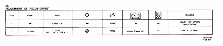
The service manual states to adjust the laser current using potentiometer R3520 and also measure voltage across R3501 for 50mv DC (attached Image 1).
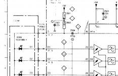
Image 2 is the reference of test points in service manual block diagram.
In the CD630 resistor R3501 is shorted with a piece of wire and I am not sure where to measure the voltage across to get 50mv DC.
Are there other test points which I can use to perform the 50mv DC adjustment ?
Or should I remove the short and replace it with a 4.7k resistor then perform the DC voltage adjustments.
Please let me know your inputs regarding the same.
Thanks in advance for your help and support.
Looking at help for laser current adjustment for the Philips CD630 CDM4/19 CD player.
The service manual states to adjust the laser current using potentiometer R3520 and also measure voltage across R3501 for 50mv DC (attached Image 1).
Image 2 is the reference of test points in service manual block diagram.
In the CD630 resistor R3501 is shorted with a piece of wire and I am not sure where to measure the voltage across to get 50mv DC.
Are there other test points which I can use to perform the 50mv DC adjustment ?
Or should I remove the short and replace it with a 4.7k resistor then perform the DC voltage adjustments.
Please let me know your inputs regarding the same.
Thanks in advance for your help and support.
Attachments
FWIW I always found Philips set up procedures a little convoluted and obscure and usually checked laser current simply by observing the RF on a scope in the normal way and confirming it met the 1.2 to 1.5 volt peak to peak amplitude.
The rationale of that approach is that ultimately the RF level and 'quality' of the signal has to be the final deciding factor.
The Philips approach relies on the average of all the photo diode currents being summed and an average current being derived from this voltage across a 'sense' resistor (the 4k7).
The Philips method is really doing a similar thing, the laser current is turned up high enough to give the desired result whether that be RF level or photo diode current.
I don't know why the resistor is not fitted to your player only to say that if it was a production change then there will be a corresponding document to detail how the adjustment should be done (or officially done") )
)
The rationale of that approach is that ultimately the RF level and 'quality' of the signal has to be the final deciding factor.
The Philips approach relies on the average of all the photo diode currents being summed and an average current being derived from this voltage across a 'sense' resistor (the 4k7).
The Philips method is really doing a similar thing, the laser current is turned up high enough to give the desired result whether that be RF level or photo diode current.
I don't know why the resistor is not fitted to your player only to say that if it was a production change then there will be a corresponding document to detail how the adjustment should be done (or officially done
)Does the resistor labelled 3502 in the schematic have a 100K resistance ? Or maybe another (higher) value ?
The resistor has a value of 104k, and not 100k as per the schematics.
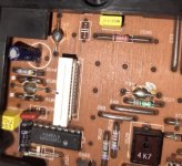
Attached the image of R3501 which is shorted labelled 248 in PCB.
The 104k R3502 resistor is a SMD resistor mounted on the rear end of the PCB.
I don't know if there are other ways to adjust the laser current.
Attachments
Last edited:
Yes, but a SMD resistor with 104 on it, has a value of 100k... ;-)
The SMD resistor though measured 104k in the multimeter.
Any pointers on how the laser current can adjusted with the short in resistor discussed above ?
Also I am not sure if this is a factory mod or something from my side.
The player though is in working condition after lens replacement, I am just looking at options to make it perfect.
This makes total sense to me.FWIW I always found Philips set up procedures a little convoluted and obscure and usually checked laser current simply by observing the RF on a scope in the normal way and confirming it met the 1.2 to 1.5 volt peak to peak
Reading all these threads about 1980’s vintage CD players with Philips optical pickups has renewed my interest in digging through my hoard of vintage hifi gear to try out several of my older CD players.
The CD player I’ll start with is a Mission PCM4000. It’s already sitting next to my workbench.
After that I’ll check out my Proton CD player (I don’t recall its model number), a California Audio Labs unit, and several Magnavox branded units. Most of these are single-disc players containing PC boards which look exactly like the typical Philips CD player PC boards. One is a Magnavox multi-disc player where the discs themselves go into a plastic box which then slides into the player.
I also have several spare Philips optical pickups, mostly CDM4 series. I don’t recall whether they are functional or not.
This should be fun!
-EB
- Status
- This old topic is closed. If you want to reopen this topic, contact a moderator using the "Report Post" button.
- Home
- Source & Line
- Digital Source
- Philips CD630 CDM4/19 Laser Current Adjustment