hi,
I'm planning to upgrade my DAC with crystek 967 oscillator and its datasheet doesn't provide anything about proper implementation of it.
it does say Load Capacitance 15pf, I would assume that a 15pf capacitor to ground should be placed on the output line (pin 3)
and should any resistor in series be placed as well?
the data-sheet is very poor,
any suggestions are welcome.
thank you.
Attachments
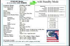
You post title says Crystek 975, then in your post's text you wrote 967, but the datasheet snippet you attached is for Crystek 957. Should I presume there are typos in your thread title and text?
If so, I can tell a little about Crystek 975. The 15pF load capacitance is what the clock is designed work optimally with. Some or all of that capacitance may come from the input capacitance of whatever chip or chips the clock may be driving.
Another thing to know about these clocks is that getting them to perform at the their best requires very carefully engineered circuit design around them, the 'implementation.' They do best with exceptionally clean power, with regulation located close to the clock on the same ground plane, using at least a 4-layer PCB, and with ground currents flowing underneath them from other electronics kept to a minimum, preferably zero. The clocks need carefully designed buffers to drive long lines and or multiple loads. Power decoupling design is critical for best performance. For clocks of it's class, it can take the 3 or 4-days of power-on time to fully warm up and stabilize for lowest phase noise. They should be located inside a solid steel case at least 18-Guage thick, or an aluminum case with walls at least 1/2" thick. If a dac design uses two clocks (one for 44.1kHz family sample rates, and one for 48kHz family) then both clocks need to be fully running at all times to maintain lowest phase noise. The clock outputs can be switched to the dac using buffer chips with an enable/disable function, or with small gold contact relays.
Implementations of these clocks without proper care and attention to small details are likely to give poor performance similar to cheap, low quality clocks.
Are you confident your electronics design skills are up to the level needed for good results with the clocks?
Last edited:
hi, yes my mistake its all about Crystek 957 obviously.
my DAC has a spdif receiver chip AK4118 and it uses an external xtal 24.576MHz, there is only one crystal, so I hope it covers all the frequencies.
Luckily Crystek makes 24.576 so that is the crystal that i want to upgrade.
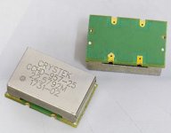
4 layer PCB would be a great option but as i can see the bottom side of Crystek 957 is fully covered with crystal's own ground plane PCB as shown on the attached photo and that in fact forms an extra pcb layer.
please let me know if i need 2 crystals of 24.576 and 22.5792 for ak4118 chip and many thanks for your answer.
my DAC has a spdif receiver chip AK4118 and it uses an external xtal 24.576MHz, there is only one crystal, so I hope it covers all the frequencies.
Luckily Crystek makes 24.576 so that is the crystal that i want to upgrade.
4 layer PCB would be a great option but as i can see the bottom side of Crystek 957 is fully covered with crystal's own ground plane PCB as shown on the attached photo and that in fact forms an extra pcb layer.
please let me know if i need 2 crystals of 24.576 and 22.5792 for ak4118 chip and many thanks for your answer.
Attachments
Accusilicon AS318B clocks have a closed metal can around them, but Topping was wise enough when designing D90 to leave a PCB copper keepout area under the clocks. Why? It guarantees no currents flow under the clock module. A thin layer of non-ferrous metal is not effective for magnetic shielding, only effective for electric field shielding (assuming clock case ground lead inductance does not make that to some degree ineffective as well). When currents are the coupling mechanism of concern, good not to forget about magnetic fields.
Regarding AK4118, it does not need an external clock, although it can be used with a local crystal as a reference used to help detect incoming sample rates.
What you might need in the way of clocking depends on what kind of dac chip is on the board and whether or not there is an ASRC chip present. Also depends if the AK4118 SPDIF recovered master clock is used for dac clocking when in SPDIF/TOSLINK mode.
Last edited:
I get it now, no currents under crystek, the ground is the way to go.
According to ak4118 data, it does not need an external clock, although it can be used and it's used often with ak4118, in my case, there is 24.576 crystal present, and the chip pins are set for above clock frequency and there isn't any ASRC and its i2s connected directly to ak4490 DAC chip.
I have already connected the new Crystek 957 with a great sound improvement result, it plays all sample rates, and quite happy with it, just wondering if I'm doing things right and searching for more improvements in implementation to get as much out of it as possible.
many thanks for all your comments very helpful!
The proper way of clocking would be to have two clocks for the dac chip, one for 44.1kHz family sample rates, and one for 48kHz family.
AK4118 SPDIF receiver can have a cheap *crystal* attached to it it as a reference to help identify incoming sample rates.
AK4137 is an ASRC and DSD converter. It works much better with a good external reference clock to help improve jitter attenuation performance during resampling. The reference clock should be the same clock currently in use by the dac chip or a buffered copy of it.
Last edited:
- Status
- This old topic is closed. If you want to reopen this topic, contact a moderator using the "Report Post" button.
- Home
- Source & Line
- Digital Source
- CRYSTEK 975