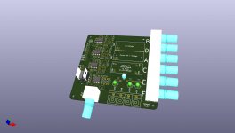
KiCAD project LASER adjustment tool PCB
Hello together!
This is my first post in this Forum and I would like to introduce myself by showing you my KiCAD project.
Building on the excellent work of ManoloMos I took his hand written schematics (two of them) and transferred them to KiCAD.
I would like to imitate his success and would like to try to repair some SONY KSS-168A Pickups.
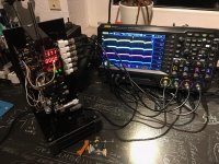
I didn't want to put all the components together on a bread board but rather do a "clean" circuit with a printed PCB Board.
Since I got a 3D printer, I would like to print a fixture for the KSS-168a and KSS-320b later.
Since I'm very new to this Laser topic I expect to have some errors in the schematic and Layout.
Maybe somebody could give me a hint and show me errors in my schematic and layout.
To drive the Laser diode while adjustment, I would like to use a LED Laser driver.
like this one here: Security Check
I have attached the schematic to this post but I have also uploaded the whole KiCad Project to my Github account and it can be found here:
Page not found * GitHub * GitHub
Hello together!
This is my first post in this Forum and I would like to introduce myself by showing you my KiCAD project.
Building on the excellent work of ManoloMos I took his hand written schematics (two of them) and transferred them to KiCAD.
I would like to imitate his success and would like to try to repair some SONY KSS-168A Pickups.
I didn't want to put all the components together on a bread board but rather do a "clean" circuit with a printed PCB Board.
Since I got a 3D printer, I would like to print a fixture for the KSS-168a and KSS-320b later.
Since I'm very new to this Laser topic I expect to have some errors in the schematic and Layout.
Maybe somebody could give me a hint and show me errors in my schematic and layout.
To drive the Laser diode while adjustment, I would like to use a LED Laser driver.
like this one here: Security Check
I have attached the schematic to this post but I have also uploaded the whole KiCad Project to my Github account and it can be found here:
Page not found * GitHub * GitHub
Attachments
Hello. I'm glad someone else imitate me, moreover, I'd like someone could improve the procedure. Some advice: Use only a voltage divider for all circuits. It's not necessary one voltage divider for each diode amplifier. The 100nf between the voltage divider and -15 was for to remove a little autoscillation.
The connection between the circuit and the oscilloscope is better with coaxial and bnc coneectors. In ebay or aliexpress are some bnc connector with cable builded.
I've seen the KSS-168A in google, and is a bit difficult to adjust the photodiode array. I think it's more difficult than in an KSS-190a or 151a. Good luck. However, if you can adjust it, it will a hope for those Pioneer Hi-End cd owners with PWY-1004 laser diode, which is very similar in dificulty.
First, practice with a functional laser pickup, seeing the signals with the oscilloscope, moving the focus lens and observating the signals, etc...
thank you for your suggestions ManoloMos!
I have changed the connectors to BNC and I have removed 3 voltage dividers.
3 voltage dividers are left but I made 2 jumpers in order to be able to use only one voltage divider.
I have also changed the power connector to the Meanwell style connector.
The updated KiCad project will be uploaded later today.
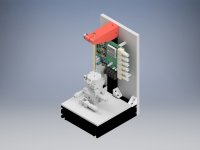
My plan is to design and print a fixture for the KSS-168A which will be mounted on a trimming platform.
The platform will be moveable in 4 axis, X, Y, Z and R.
This one: XYZR Axis 40*40mm 4 axis V Type Trimming Platform Manual Linear Stage Bearing Tuning Sliding Table LTP40 L XYZR40 L 9.8N|sliding table|linear stagelinear slide table - AliExpress
Very fine adjustments should be possible with such a platform.
Also I think that I will build a frame out of 3030 profiles to put the platform on with the PCB and power supply.
I hope that this will increase my chances to succeed.
I bought 10x10mm Mosaic glas plates and would like to use them as a mirror.
But I am not sure about how precise I have to place the glas in order to avoid angular error.
The idea is too glue this Mosaic to the plastic cap and use it this way for adjustment. And and when the adjustment is done, to replace the plastic cap again against the original cap.
I have changed the connectors to BNC and I have removed 3 voltage dividers.
3 voltage dividers are left but I made 2 jumpers in order to be able to use only one voltage divider.
I have also changed the power connector to the Meanwell style connector.
The updated KiCad project will be uploaded later today.
My plan is to design and print a fixture for the KSS-168A which will be mounted on a trimming platform.
The platform will be moveable in 4 axis, X, Y, Z and R.
This one: XYZR Axis 40*40mm 4 axis V Type Trimming Platform Manual Linear Stage Bearing Tuning Sliding Table LTP40 L XYZR40 L 9.8N|sliding table|linear stagelinear slide table - AliExpress
Very fine adjustments should be possible with such a platform.
Also I think that I will build a frame out of 3030 profiles to put the platform on with the PCB and power supply.
I hope that this will increase my chances to succeed.
I bought 10x10mm Mosaic glas plates and would like to use them as a mirror.
But I am not sure about how precise I have to place the glas in order to avoid angular error.
The idea is too glue this Mosaic to the plastic cap and use it this way for adjustment. And and when the adjustment is done, to replace the plastic cap again against the original cap.
Attachments
I took a look at the photodiode under the microscope (picture attached).
Elements A,B,C and D are clearly visible under the microscope.
I assume that the two outer elements are the Diodes E and F.
Compared to A,B,C and D they are very larger hence maybe the reason why they are easy to find.
I tried to clean the Photodiode array with alcohol and a q-tip but ended up scratching the surface.
I tried to find a new Photodiode array but was not successful: does anybody know where this Photodiodes can be bought new?
Attachments
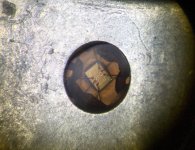
Hi. I've cleaned the photodiode array window with alcohol and cotton, and is very strong. Try to clean another time, maybe is dirty. If you think the photodiode is bad, you can replace it with another from sony KSS similar photodiode, genuine or clone. Buy a cheap KSS Sony clon laser pickup with a photodiode array. Or if in this forum is someone with this spare part... There are different manufacturers, but are equivalents. When you work, you can make mistakes. Only who do not do nothing, does not make mistakes. I burned a photodiode array from a KSS-272A, I mistake the Gnd pin with V/2 pin. This things happens.
And yes, four tiny squares are abcd diodes, and the other ones are E and F. As you can see, are very very small. If you see a photodiode array from OPH-31 or similar, the size are gigantic compared to KSS photodiodes.
Another thing, if the picture is from the damaged photodiode with alcohol, it looks ok. Try to test first before replace photodiode.
I think it is already too late to build a cheap prototype. ")
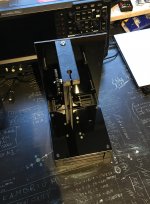
I have already ordered all parts and have already completed the frame.
Waiting for the PCB and trim table now to finish everything.
I wonder how SONY made all this adjustments in the factory.
Did they do it like ManoloMos did it or did they used some other method?
I wonder if they adjusted the grating lens because it is also glued.
They focus lens assembly is also glued and therefore was probably adjusted as well.
Attachments
Yes, grating is adjusted, or better said, it must be adjusted, but I don't know how. In pioneer P-D70, the grating is adjusted with a cd playing with test mode. So, the best option: Do no touch grating.
About your "adjust rig", practice with a working laser pickup and try to find the signal. If signal doesn't appear, try another mirror.
About your "adjust rig", practice with a working laser pickup and try to find the signal. If signal doesn't appear, try another mirror.
Thanks for the useful hints ManoloMos!
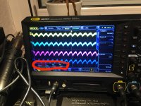
Finding the signals is not very hard. I can find them within one minute.
The "perfect" adjustment take a bit longer.
Yesterday I found all signals and adjusted all Peak-to-Peak signals for the same level. After that i glued the Photodiode cell and left it for the night.
earlier this morning I tested again and I could see that there seems to have been some drift over the night.
For now I would call it a 50% success.
I´ve installed a new Laserdiode and adjusted the Photodiode array.
When I put the Laser pickup back into the CD Player I can see a signal but it is not able to play Music.
Like you, I used a Rohm Laser Diode.
I can see that the signal lines seem to be more straight.
It seems to me that the signal is more precise.
Like you, I have also noted that I have to turn down the power of the laser diode.
But when I turn it down to 1.0 or 1.1 Volts I can see that signal start to be shaky.
Hmm.. maybe one cause could be the E-F Diodes .. I have only adjusted them to roughly 15% voltage deviation
Yesterday I have ordered some AD826 Opamps in the hope to get rid of the noise I currently have.
I used cheap Audio Opamps..
But noise could also be caused by the PCB (2Layer only) or Power supply.
I have noticed that my Power supply is out of the manufacturers spec list.
Currently the power supply has 500mV peak to peak noise.
I think it is about time to start my own Thread.. sorry for hijacking yours
Attachments
500mV is a very high noise level for power supply rails. Especially for power supplied to analog circuitry.But noise could also be caused by the PCB (2Layer only) or Power supply.
I have noticed that my Power supply is out of the manufacturers spec list.
Currently the power supply has 500mV peak to peak noise.
I think it is about time to start my own Thread.. sorry for hijacking yours
Today analog circuit designers frequently add small linear LDO (low dropout) voltage regulator IC chips located physically close to the opamps and other sensitive analog circuitry. By adding local linear LDO regulators the residual power rail noise can be reduced to microvolts.
The incoming raw power supply voltages should be set 2-3V higher than the desired low-noise power rails for the analog circuits.
Example: Analog circuit requires +/-12V DC. Raw input voltages can be +/- 14-15V. There won’t be much power wasted in these linear regulators because their voltage drop is <3V. Therefore the linear LDO regulators can usually be in tiny SOT-23 packages.
-EB
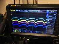
For now I think that I have achieved a useable condition.
I have changed the OpAmps to AD826 and it did reduce the noise level. -> picture attached.
Also I have added a ripple Filter circuit.
Now I got 150mV at +15 and -15V and 50mV at 5V.
I have changed two Laser diodes now. I'm not very happy with the result since the playback is not clean, it has a lot of scratching noises.
So I assume that the Laser diodes never have been the main problem.
Next I will try to change the photodiodes.
I noticed on one pickup that I was not able to balance al Photodiodes equally.
I wonder what also could be damaged.. maybe mirrors..
Thanks for the Idea to use LDO´s I think I will give it a try.
With the added ripple filter, I have reduce the Voltage to approx +/-12V.
However, I used the simplest ripple filter circuit, maybe I should also try to optimise it first.
Attachments
Hi. For to glue the photodiode array, I used glue with two compounds mixed, and wait one or two days, without remove the laser pickup from the "adjustment rig". If you don't touch nothing, the wave signal must be equal. As you can see, as can be with the original laser or the repaired laser, the wave can change when you move the laser in the rig. This is normal. Once you install the laser pickup, you must adjust the angle with the two or three screes below the lens. This is not easy, but the signal can be improved a lot with this adjustment.
The problem with the noise in from the laser diodes can be easy, or a nightmare. A clean power supply is important. I used a cheap MW Mean Well +-15V, and the result is pefect. It appeared a tiny autoscillation and was eliminated with 100nf capacitor between -15 and the potentiometer for to remove DC voltage at output.
I've realized that the adjustment of Focus, Tracking, etc... is more delicate in laser pickups with only photodiodes in the array, like KSS-190A, 151A, etc... In the KSS-271a, ,272A and etc... the adjustment and the performance is a bit better.
And no, it is not easy, but is fun and enjoyable, though sometimes I've been angry.
Hello,
Here are some pics of the frame I made for the KSS151


I'm using the same XYZR table as Ruzki.
I managed to adjust my first KSS151

It works fine.

I have more difficulties with the second one.
On the first one I only changed the laser diode, but on the second one
I have also replaced the flexible ribon cable because it was damaged.

Now I think I have to learn how to adjust the screws under the lens because the second KSS is only playing the first half of the disk ...
Here are some pics of the frame I made for the KSS151
I'm using the same XYZR table as Ruzki.
I managed to adjust my first KSS151
It works fine.
I have more difficulties with the second one.
On the first one I only changed the laser diode, but on the second one
I have also replaced the flexible ribon cable because it was damaged.
Now I think I have to learn how to adjust the screws under the lens because the second KSS is only playing the first half of the disk ...
WOW! Nice work! Funny you had the same idea.
Can you give us some details about the dip30 circuit on top of your Board and also some details about your power input.
It seems like you have implemented some sort of input filter.
Interesting that you and ManoloMos have this distinct pattern of the photodiodes.
My waveform does not look a bit like yours.
Maybe it is because if have my coils hanging of the side.
In the pictures it seems to me that you have also changed the photodiode... correct?
Hi Ruzki,
The schematic I used is the one that Manolomos published and it is the same you used also.
What I added is a SONY CXA1081, it is the IC that can be seen on the board. I'm using only the APC power supply function for the laser diode.
For the power supply I'm using a dual lab power supply but I added on the PCB a LM7815 and a LM7915 with usual filtring.
There is no other filtring on the inputs.
At today I worked on 2 units.
On the first one I only replaced the laser diode. This one is working very well.
On the second one I had to replace the flexible PCB because the original was damaged. That means that I had to desolder the photodiodes array and remonted it on the new PCB. To do that I had to remove the optical bloc from the black plastic frame and it is certainly why now a have to readjust its the position by the mean of the two srews located near the aluminium bloc. This bloc is actualy reading the CD only on the very first tracks.
It is important to remember that the diffracting grid is creating a diffraction patern that meens that there is a central spot with a certian number of lateral spots. The central one and the most intens of them must hit the ABCD cells and the first one on each side is for E and F.
To be sure that the aligment is correct it is important to check that the instensity of the light received by E and F is almost the same. Because it can happend that for instance the central spot is on E, the first lateral spot on ABCD and the second lateral spot is on F.
So here are some constatations on the best way to adjust the photodiodes array :
- with the laser diode turned OFF, adjust the DC output value of the 6 amplifiers ABCDE and F to be close to 0V.
- turn the laser ON and apply the voltage to the focus coil
- first adjust the photodiodes array in X Y and R in the way to obtain the same DC value on E and F output.
- if it is correct, a very small action on X Y and R must lead to the good patern for ABCD. The AC value must be as close as possible but also the DC value must be close. For achiving this it is important to be in DC coupling on the scope.
The DC voltage applied to the focus coil is very important and must be readjusted during the procedure. This is due to thermal drift of the 2 transistors output stage. It is why a good adjustment abtain after some hours of hard work can looks bad after a night of rest.
Hi Guys as an owner of 2 Sony CDP227esd, I am watching this with great interest. I really think you guys are really talented and should go into business selling restored laser Lenses. There is I believe still a Huge market for people whom love their CD players but are disappointed by the cheap imitations from China.
I would be happy to pay good money to have a spare laser for my Players, But I am not willing to take the risk of the China ones.
Again Bravo to all 3 of you.
regards from Australia.
I would be happy to pay good money to have a spare laser for my Players, But I am not willing to take the risk of the China ones.
Again Bravo to all 3 of you.
regards from Australia.
- Home
- Source & Line
- Digital Source
- KSS-190A with new laser diode. Applicable for the KSS-151A too.