Good evening!
I made myself a device for AKM 4493
Ideology:
- available components that can be purchased within a maximum of a week
- simple circuitry
- 2 layer board
- the presence of a repeater for headphones on the DAC board
- the presence of rectifiers on the DAC board
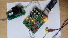
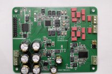
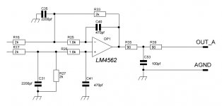
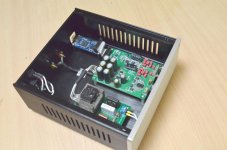
The board contains: a power supervisor (practice has shown that extra 2-3$ greatly improves the stability of the board startup), galvanic isolation for I2S and I2C, power supply for AMS1117 / LM317 / LM337 and power supply for VDD DACs for LP2985, LPF 3 orders for LM4562 and repeater on TPA6120A2.
I2S / I2C input connector - Amanero. The board allows you to enable IC DAC both in Parrallel control mode and in Software. For configuration, the board has pull-up resistors to VDD and VSS, respectively. I set up the I2C control, I had to tinker a bit with the amanero firmware, in the end it works.
I used WIMA capacitors, but in theory you can use NP0 ceramics with 5mm lead spacing. The sound of the LM4562 compared to the same NE5532 seemed softer in the bass area.
The board is powered by one transformer TP112-4, heating is tolerable. At the input, the simplest filter on the common mode choke, resistor and capacitor.
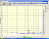
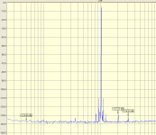
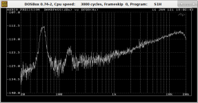
Measurements. For measurements, I used Julia @ ADC AK5385, it seems that it does not allow to fully assess the characteristics of the resulting board.
The result of SINAD = 111 dB is just a little short of the passport values (THD + N = -113 dB), although it may just be the limit of the measuring card, the cable is simple, RK 75, it is quite possible if you make the cable better / shorter then 50 Hz will disappear , although there is below -130 dB, in principle, you can not worry too much.
I made myself a device for AKM 4493
Ideology:
- available components that can be purchased within a maximum of a week
- simple circuitry
- 2 layer board
- the presence of a repeater for headphones on the DAC board
- the presence of rectifiers on the DAC board
The board contains: a power supervisor (practice has shown that extra 2-3$ greatly improves the stability of the board startup), galvanic isolation for I2S and I2C, power supply for AMS1117 / LM317 / LM337 and power supply for VDD DACs for LP2985, LPF 3 orders for LM4562 and repeater on TPA6120A2.
I2S / I2C input connector - Amanero. The board allows you to enable IC DAC both in Parrallel control mode and in Software. For configuration, the board has pull-up resistors to VDD and VSS, respectively. I set up the I2C control, I had to tinker a bit with the amanero firmware, in the end it works.
I used WIMA capacitors, but in theory you can use NP0 ceramics with 5mm lead spacing. The sound of the LM4562 compared to the same NE5532 seemed softer in the bass area.
The board is powered by one transformer TP112-4, heating is tolerable. At the input, the simplest filter on the common mode choke, resistor and capacitor.
Measurements. For measurements, I used Julia @ ADC AK5385, it seems that it does not allow to fully assess the characteristics of the resulting board.
The result of SINAD = 111 dB is just a little short of the passport values (THD + N = -113 dB), although it may just be the limit of the measuring card, the cable is simple, RK 75, it is quite possible if you make the cable better / shorter then 50 Hz will disappear , although there is below -130 dB, in principle, you can not worry too much.
Attachments
Looks like a nice design, but perhaps with some room for improvements.
What output level did you use for the THD measurement (in dBFS)?
What op-amps did you use? The PCB seems to contain 2 devices in SOT23-5 packages.
Did you use the LP2985 also for the reference voltages of the DAC? The LP2985 is relatively noisy.
Did you pass the MCLK through the isolator? If so, some jitter will be added.
Looks like a nice design, but perhaps with some room for improvements.
What output level did you use for the THD measurement (in dBFS)?
What op-amps did you use? The PCB seems to contain 2 devices in SOT23-5 packages.
Did you use the LP2985 also for the reference voltages of the DAC? The LP2985 is relatively noisy.
Did you pass the MCLK through the isolator? If so, some jitter will be added.
Hi!
Output level for the THD measurement is 1VRms.
LP2985 is a good choice in this situation, if you additionally install a noise-canceling capacitor on leg 4. An additional RC filter is also made for Vref.
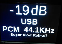
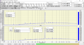
The ideology of the board assumed a minimum of rare components. Therefore, the generators are used from the amanero board. No noticeable deterioration in sound quality was noticed.
I have experience of using low-quality generators, as in the attached picture. This is also not noticeable by ear.
Attachments
AK4493 is an improved version of AK4490, so it is ideal for building an inexpensive converter.
Undoubtedly, AK4497 will sound better with a more careful approach, but the cost of the finished product will be many times higher.
I have not seen AK4496 chips either on sale or on the manufacturer's website.
Now I'm expecting an AK4498 with an external modulator. But this will already be a modular design.
The AK4495 chip is rather outdated and has a more pronounced color in sound, so in this design I preferred the newer AK4493. It is also possible to install AK4490 on this board (subject to changing the settings of i2c of the amanero board)

Very nice design. If I may I make some critical remarks:
- Please note that many LM4562 exhibit popcorn noise. I don't know if they solved it but when it starts to occur after some time it will stay that way.
- AMS1117 is not the best regulator one can find. It is one of the noisiest with 100 µV noise. I don't know if using a better one will improve the already good results but I avoid any AMS1117/LD1117.
Are those black caps polymer caps?
Last edited:
cap
There is an idea to make a new design with some improvements.
As a power supply, you can of course use the LP2985, but I'm afraid there will be no big difference in comparison with the AMS1117, this stabilizer only feeds the digital part. I made a choice in favor of tantalum capacitors in the power supply and film in the signal circuits, experience showed a difference in sound quality and slightly better technical characteristics of the resulting device, in favor of tantalum capacitors. Therefore, electrolytes remain only in those places where it is difficult or undesirable to use tantalum.
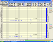
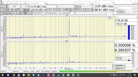
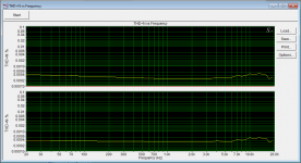
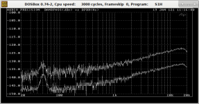
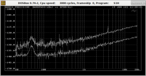
I conducted several experiments with the general power supply of the device. In the pictures, SNR with A weighting and measurements of absolute and relative noise levels using Audio Precision.
There is an idea to make a new design with some improvements.
As a power supply, you can of course use the LP2985, but I'm afraid there will be no big difference in comparison with the AMS1117, this stabilizer only feeds the digital part. I made a choice in favor of tantalum capacitors in the power supply and film in the signal circuits, experience showed a difference in sound quality and slightly better technical characteristics of the resulting device, in favor of tantalum capacitors. Therefore, electrolytes remain only in those places where it is difficult or undesirable to use tantalum.
I conducted several experiments with the general power supply of the device. In the pictures, SNR with A weighting and measurements of absolute and relative noise levels using Audio Precision.
Attachments
Hi i am afraid that an assumption is better avoided. The costs of very good regulators are small relative to the total cost.
I also think modern tantalum capacitors are good depending on which brand and series. The drop type caused a lot of harm and destructed their reputation but modern ones are just fine regarding quality and reliability.
What are we looking at in the graphs? Lower noise because of what choice of what capacitors (at what spot)?
Last edited:
I forgot to write explanations to the graphs, on the graphs the parameters of the DAC with a laboratory power supply, to reduce the network interference of 50Hz and harmonics. One of the ideas for the new board is to power DC-DC converters, as I did on the ADC, in order to minimize the level of its own interference. The cost of the fee will increase accordingly, approximately 2 times 
Unfortunately, there are no graphs with experiments left, since the experiments were conducted 3 years ago on other boards. This fee is the result of accumulated experience. There are also results of using a more expensive element base in my ADC project
USB ADC on Cirrus Logic CS5381
Unfortunately, there are no graphs with experiments left, since the experiments were conducted 3 years ago on other boards. This fee is the result of accumulated experience. There are also results of using a more expensive element base in my ADC project
USB ADC on Cirrus Logic CS5381
Last edited:
- Status
- This old topic is closed. If you want to reopen this topic, contact a moderator using the "Report Post" button.
- Home
- Source & Line
- Digital Source
- DIY DAC AK4493