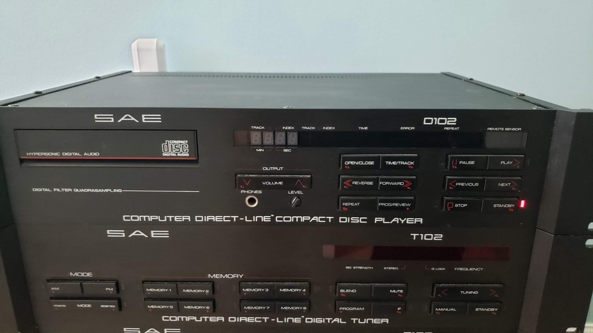
The Corona pandemic gives me reason to stay indoors and burn up some brain cells trying to fix a problem which seems to plague a lot of SAE CD Players. Often the digital display will lose segments or go completely dead. Unfortunately the display is not just simple 7 segment LED's. It is a complex self contained unit that communicates serially with the main board. When it goes bad it is not really repairable. The chip on it looks like a glob of glue. This part is unobtanium. I have tried to negotiate research with the manufacturer and they tell me it is too old to research.
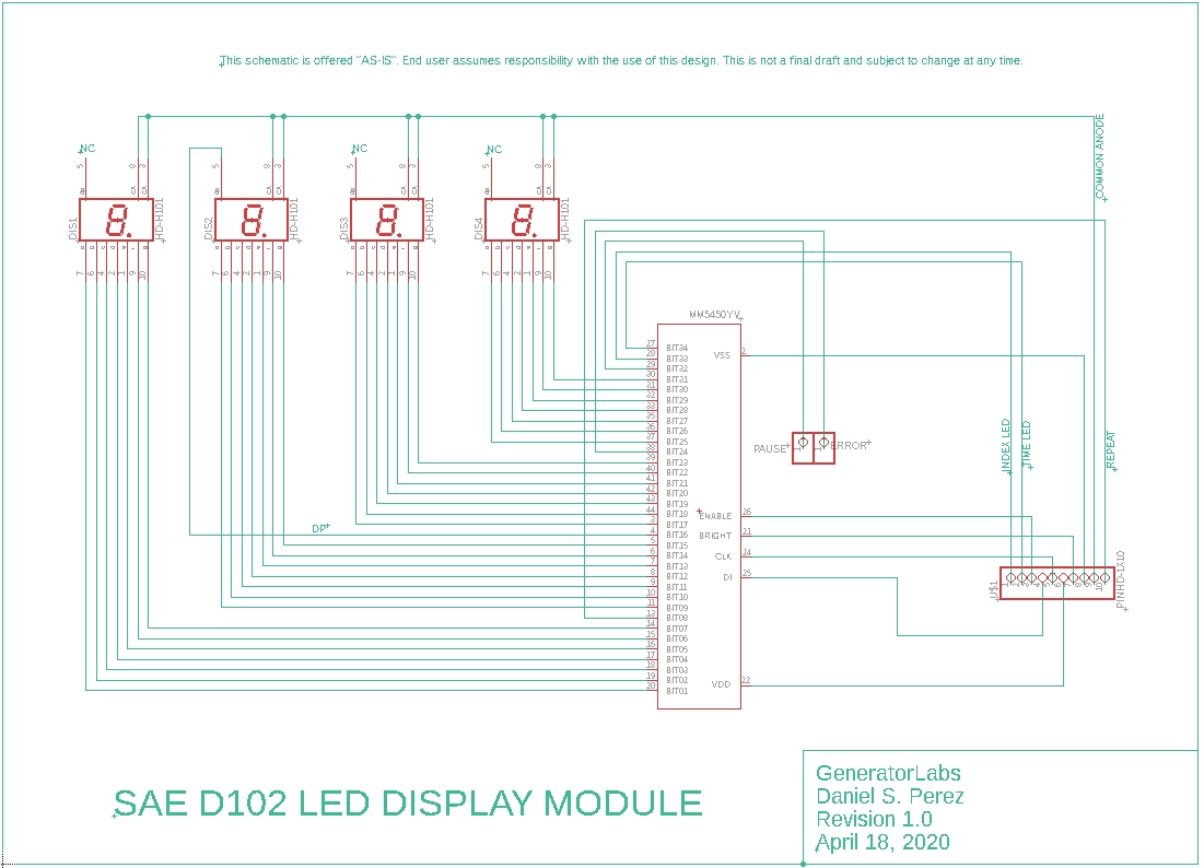
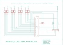
The SAE D102 is based on a Phillips/Magnavox chassis. The Phillips/Mag players tend to exhibit similar problems and use Green LEDs instead of Red. I was inspired when I saw that someone in the Netherlands had reverse engineered the display module for a Phillips unit. I actually tried to contact that person but my questions failed to get a response. I can understand when people don't want to share their hard work so I decided to reverse engineer the SAE display module on my own. The SAE variant is a little different. It has more pins (12 instead of 9 or 10) and addresses all 35 display bits to not only update four 7-Segment LED's but also drive 5 other stand-alone LED's such as Pause, Error, Index, Time and Repeat.
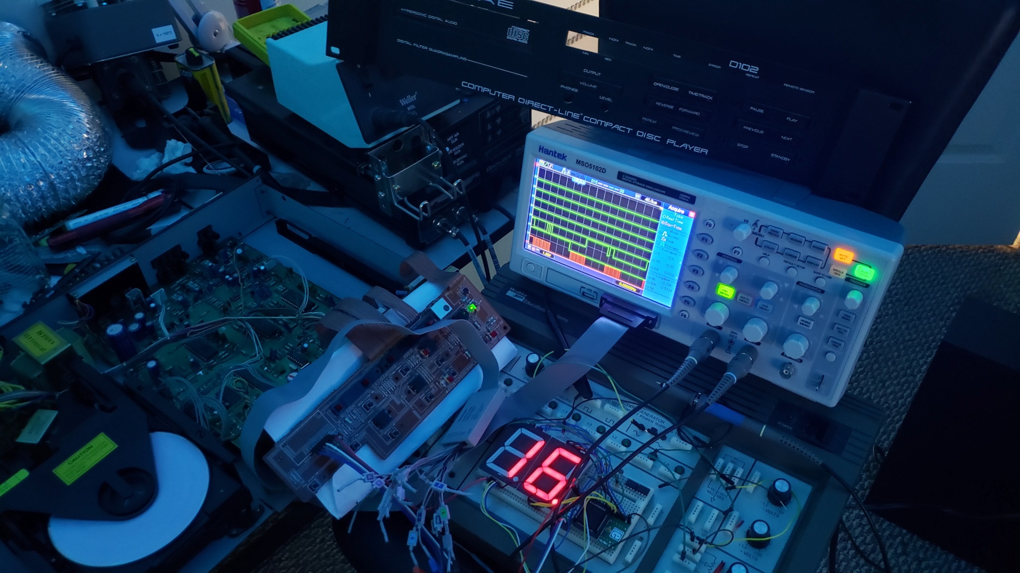
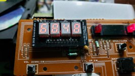
I made some progress this evening. In the photo you can see that I have at least two of the four 7-Segment LED's working on some mock-up jumbo LED modules. Once you solve the equation for 2 digits the others are easy to figure out.
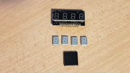
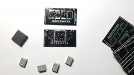
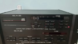
The second photo shows the original module from @ 1987. Below the module are the new IC and 7-Segment LEDs that will replace it. I have to finish drawing the printed circuit board in CAD and then I will get a number of PCB's printed up for formal testing. It will be a long process but time is in abundance lately!

The SAE D102 is based on a Phillips/Magnavox chassis. The Phillips/Mag players tend to exhibit similar problems and use Green LEDs instead of Red. I was inspired when I saw that someone in the Netherlands had reverse engineered the display module for a Phillips unit. I actually tried to contact that person but my questions failed to get a response. I can understand when people don't want to share their hard work so I decided to reverse engineer the SAE display module on my own. The SAE variant is a little different. It has more pins (12 instead of 9 or 10) and addresses all 35 display bits to not only update four 7-Segment LED's but also drive 5 other stand-alone LED's such as Pause, Error, Index, Time and Repeat.
I made some progress this evening. In the photo you can see that I have at least two of the four 7-Segment LED's working on some mock-up jumbo LED modules. Once you solve the equation for 2 digits the others are easy to figure out.
The second photo shows the original module from @ 1987. Below the module are the new IC and 7-Segment LEDs that will replace it. I have to finish drawing the printed circuit board in CAD and then I will get a number of PCB's printed up for formal testing. It will be a long process but time is in abundance lately!
Attachments
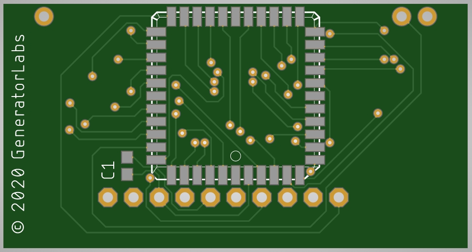
I finished my CAD drawings and sent them off to a board shop in China to be produced. Keeping my fingers crossed that I have not missed any mistakes. I should have them in 14-21 days.
Attachments
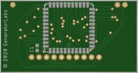
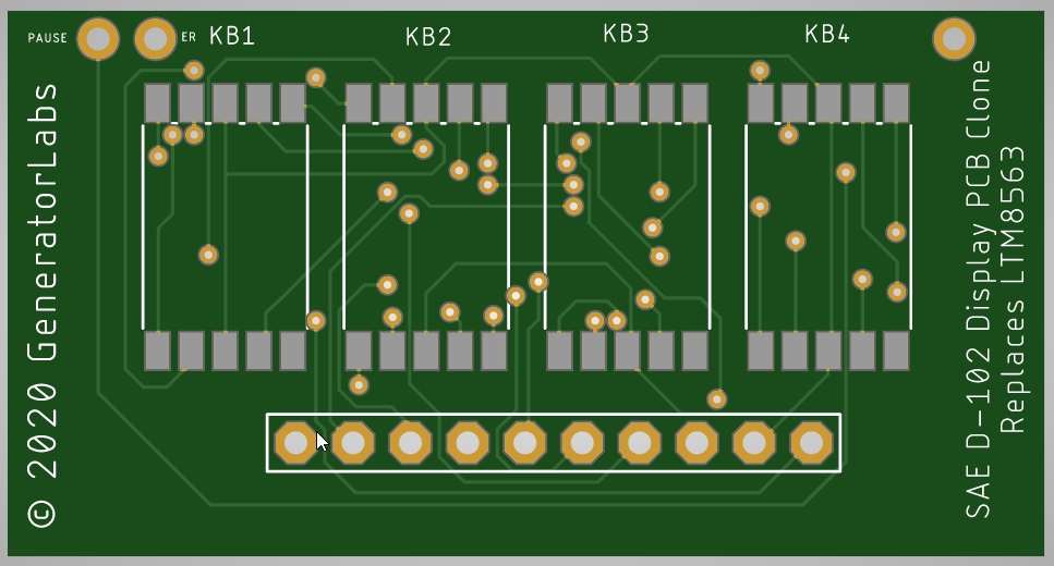
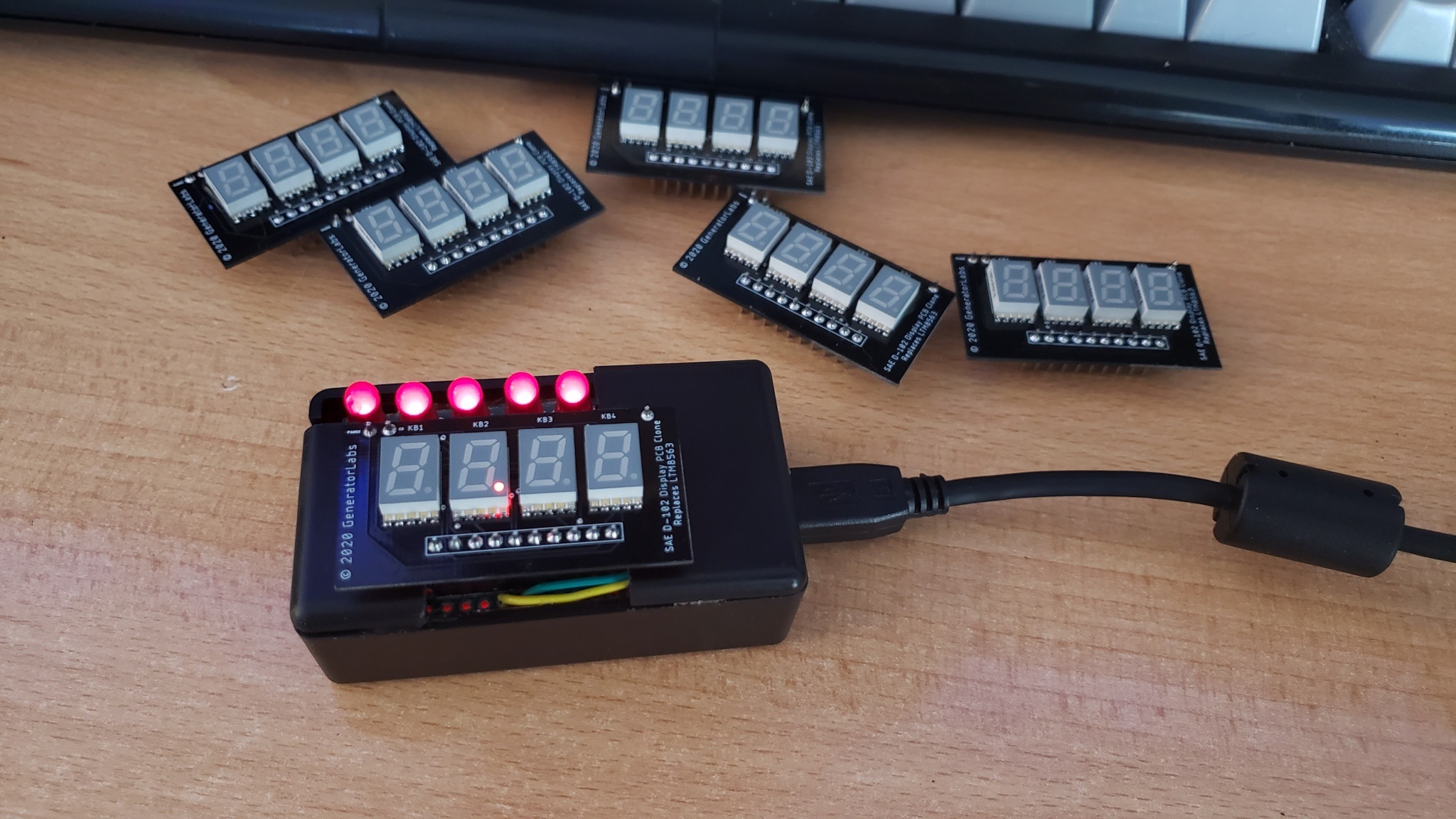
Here is an update regarding the SAE D102 display board. I sent my CAD files off to China less than 2 weeks ago. They came in on Friday evening so I was quite excited to see if all that design time would pay off. I am happy to say that it works well and this design is now a pin-perfect replacement to the original 80's era LTM8563 board. I like to call it a "clone" of the original board, but using modern components.


Attachments
Thank you for your kind words.
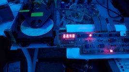
This is what the clone board looks like once installed in the bezel. The grey color of the new 7 segment LED's does not offend me too much. I would have preferred black but that is not an option, at least for now. Another member suggested using photographic filter film to black it out which is a great idea. Due to the way the internal black plastic frame is manufactured it is a very possible option. The frame is slightly recessed in the area where the LED's sit so it forms a perfect transition point for a filter. I already have a D102 and this is not a unit I intend to keep so the new owner can attempt it. On a side note, I assume this device must have been an overseas unit because it has two separate voltage select switches. One for the primary transformer and one for the standby transformer. I don't think I have seen a D102 in this configuration or maybe I just never really noticed. It seems crazy that they would have two separate switches for that!
This is what the clone board looks like once installed in the bezel. The grey color of the new 7 segment LED's does not offend me too much. I would have preferred black but that is not an option, at least for now. Another member suggested using photographic filter film to black it out which is a great idea. Due to the way the internal black plastic frame is manufactured it is a very possible option. The frame is slightly recessed in the area where the LED's sit so it forms a perfect transition point for a filter. I already have a D102 and this is not a unit I intend to keep so the new owner can attempt it. On a side note, I assume this device must have been an overseas unit because it has two separate voltage select switches. One for the primary transformer and one for the standby transformer. I don't think I have seen a D102 in this configuration or maybe I just never really noticed. It seems crazy that they would have two separate switches for that!
Attachments
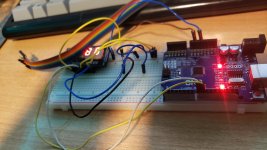
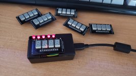
As I was sitting around drinking coffee, one thing that occurred to me is the ordeal involved with dismantling and installing this device. How upset would you be if you went through all of that work and something was not right with the new LED display? Or even worse if there was a bridged solder joint that caused a different failure? It is a scary thought indeed. Since I do not have the desire to keep a spare D102, with its guts perpetually exposed, I decided to build a "Testing Aparatus" for every display module I build. With the testing device I can simply drop each completed module in a specially crafted socket that will run the LED display module through its paces. Every LED segment will be lit via a series of number patterns. All of the auxiliary LED's controlled by the module will be tested as well. This is a photo of my mock-up testing device. It is basically an Arduino with some code I put together to mimic the data stream from a D102. It works very well and I will construct a formal unit once I receive some parts I ordered.

Attachments
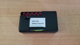
Testing Jig Complete
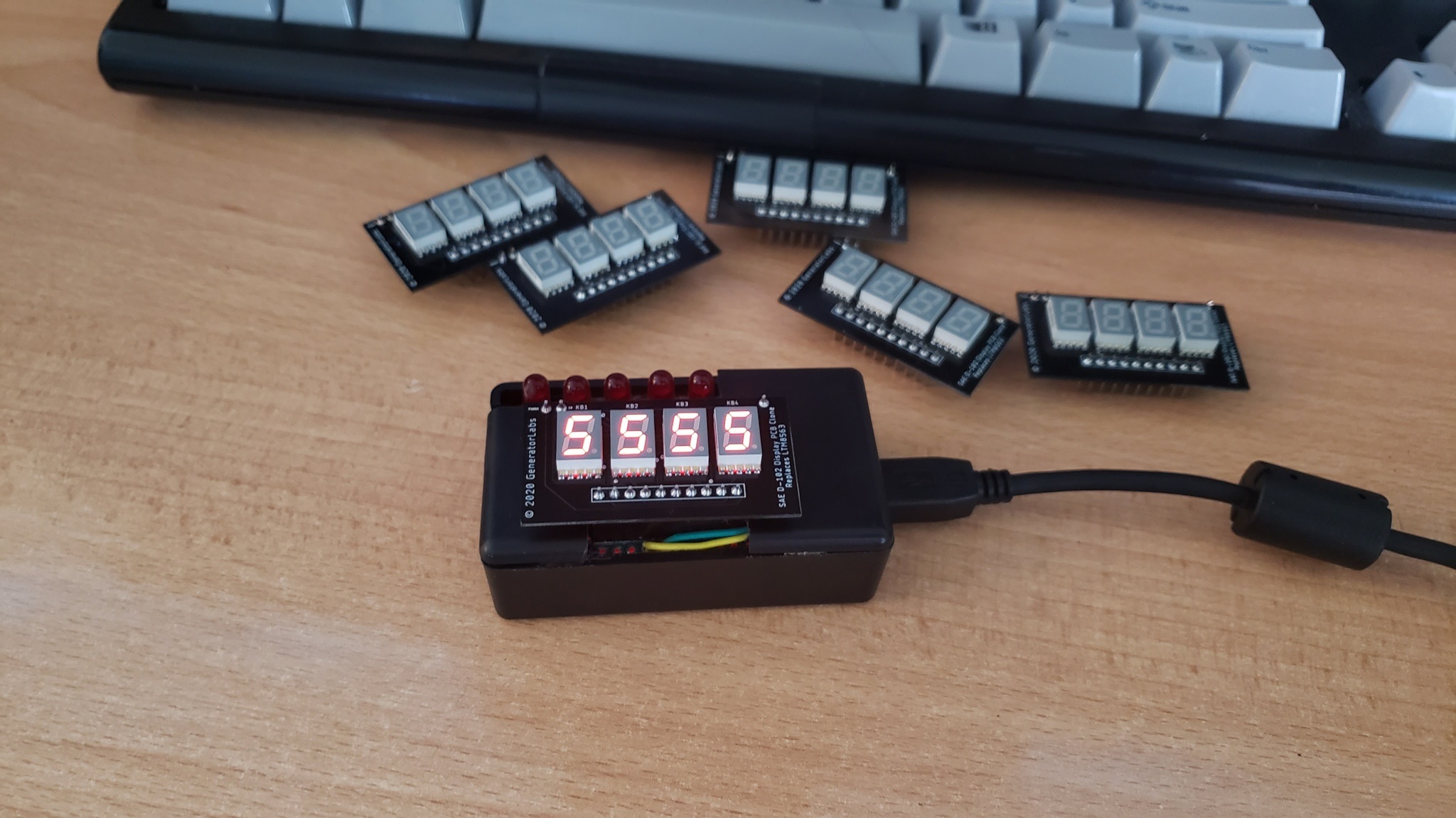
This is my finalized version of the testing jig.
Inside is an Arduino Nano running some code I threw together to mimic the data stream from a D102 player. The USB cable is there to supply power.
This will ensure every module I produce leaves in working order!

This is my finalized version of the testing jig.
Inside is an Arduino Nano running some code I threw together to mimic the data stream from a D102 player. The USB cable is there to supply power.
This will ensure every module I produce leaves in working order!
Attachments

One day I would like to send you the C101 3-head cassette deck that I disassembled in 1998 to change the belt...
What is the problem with the deck?
It was acting like a belt was stretched (can't remember exactly), and I thought it would be straightforward to replace the belt, but after digging it apart for a while, the belt still remained inaccessible. Then I got access to a CD burner, put a CD player in the car, and never looked back on those rotten tape thingies again....
It was acting like a belt was stretched (can't remember exactly), and I thought it would be straightforward to replace the belt, but after digging it apart for a while, the belt still remained inaccessible. Then I got access to a CD burner, put a CD player in the car, and never looked back on those rotten tape thingies again....
I could do it but I bet the shipping on that unit would be a small fortune. I don't remember the 101 exactly being lightweight.
It would be a gift to you, if you cover shipping from Florida and can wait a few months...!
If all the parts are there and it looks decent, I would be willing to take a gamble. Let me know when you have time to work it out.
Thanks
Hi Andersonix. In case you still have this deck I‘d be happy to pay shipping. I could use some spares for mine.Glad to send it to someone who appreciates it! Will PM you about it, but it won't be until later this year...
Yes I still sell these. If you search for "D102 LED" on the bay you will find them.
I will admit the sales of these have diminished over the past few months.
Got me wondering if people even listen to CD's anymore.
I do. I just bought another bad D102 the other day. All it needed was a display module.
I cringe at how many of these things just got dumped because the display was unobtainium.
- Home
- Source & Line
- Digital Source
- SAE D102 - Reverse engineering LED display module