Hi there all,
I own sinds many years, a Cambridge Azur 840C Cd Player/DAC , which has shown quite some problems, mostly due to poor quality Chines Electrolytic capacitors (the problems All being located at the power lines of the DAC's (AD155 's) the Op AMP's and the Muting circuit.
The digital sections have so far worked flawlessly.
I would like to address this problem of poor electrolytic capacitors in All powerrails once and for all, instead of having to repair it about every 3 years.
(Once it works, it sounds very nice, hence I'm still holding on to it).
MY question:
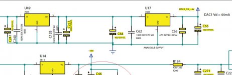
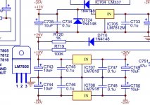
There are a total of 21! voltage regulators (Type LM78xx, LM79XX, LT1761, LT1763, LM1117, each with a 10uF 35V capacitor at the Input and Output.
These 10 uF 50V capacitors have a short lifetime expectation due to poor quality, but also because they are mounted immediately next to hot heat sinks (a clear design error) and also due to poor ventilation possibility (due a suboptimal enclosure design), resulting into high operating temperatures inside the enclosure.
Better quality capacitors (e.g Rubycon 105 deg. C) typically behave better, but I am contemplating to cure this problem Once and for All, by using film capacitors e.g. 2.2 uF or 3.3. uF 50V WIMA MKS Polystyrene capacitors.: MKS2B043301H00KSSD WIMA - Capacitor: polyester | 3.3uF; 30VAC; 50VDC; Pitch: 5mm; +-10%; MKS2-3.3U/50 | TME - Electronic components
In view of space limitations, I cannot use higher values (I already have to install them at the bottom side of the board).
Could you please confirm whether such a lower value (3.3 uF film capacitor instead of a 10 uF electrolytic could work ( I have read somewhere that they are only used to suppress possible oscillations of the voltage regulator).
Please note that the 5 main power supply rails are each buffered with 4400 uF 50v (each 2x 2200 uF capacitors).
Appreciate your opinion / feedback!
I own sinds many years, a Cambridge Azur 840C Cd Player/DAC , which has shown quite some problems, mostly due to poor quality Chines Electrolytic capacitors (the problems All being located at the power lines of the DAC's (AD155 's) the Op AMP's and the Muting circuit.
The digital sections have so far worked flawlessly.
I would like to address this problem of poor electrolytic capacitors in All powerrails once and for all, instead of having to repair it about every 3 years.
(Once it works, it sounds very nice, hence I'm still holding on to it).
MY question:
There are a total of 21! voltage regulators (Type LM78xx, LM79XX, LT1761, LT1763, LM1117, each with a 10uF 35V capacitor at the Input and Output.
These 10 uF 50V capacitors have a short lifetime expectation due to poor quality, but also because they are mounted immediately next to hot heat sinks (a clear design error) and also due to poor ventilation possibility (due a suboptimal enclosure design), resulting into high operating temperatures inside the enclosure.
Better quality capacitors (e.g Rubycon 105 deg. C) typically behave better, but I am contemplating to cure this problem Once and for All, by using film capacitors e.g. 2.2 uF or 3.3. uF 50V WIMA MKS Polystyrene capacitors.: MKS2B043301H00KSSD WIMA - Capacitor: polyester | 3.3uF; 30VAC; 50VDC; Pitch: 5mm; +-10%; MKS2-3.3U/50 | TME - Electronic components
In view of space limitations, I cannot use higher values (I already have to install them at the bottom side of the board).
Could you please confirm whether such a lower value (3.3 uF film capacitor instead of a 10 uF electrolytic could work ( I have read somewhere that they are only used to suppress possible oscillations of the voltage regulator).
Please note that the 5 main power supply rails are each buffered with 4400 uF 50v (each 2x 2200 uF capacitors).
Appreciate your opinion / feedback!
My advice would be to stick to the original values and type (electrolytic) but obviously use top quality 105C or even 125C rated parts.
That said, nowhere on the board should be any near those temperatures. Using low impedance caps on the output of some regulators can in some cases cause stability issues rather than fixing them. Stick to the original design.
That said, nowhere on the board should be any near those temperatures. Using low impedance caps on the output of some regulators can in some cases cause stability issues rather than fixing them. Stick to the original design.
Hi Mooly,
Many thanks for your comments!
However, unfortunately, I have become wary some parts of the design of the AZUR 840C because I already discovered some design errors (leading to failures which many people reported/suffered).
e.g.
One was that after some 2-3 years the muting relais of the audio started to misbehave (erratic switching , los of a channel and noise).
There was a factory memo indicating to replace a 470 uF 16V smoothing capacitor (reported to fail prematurely) behind a resistor to dissipate 10V to 5 V (Cambridge recommended to upgrade to 470 uF 63V, but did not notice that they had made a design error).
(In the AZUR 740C they only used 1 muting relay;
However, in the 840C they used 3;
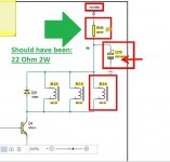
Hence the 62 Ohm serial resistor of the 740C design (which was correct for one Massuse Me2-5 relay) was not adapted (to a calculated 22 Ohm for 3 relays in the 840C, resulting into only 75% of the nominal voltage for these muting relays in the 840C).
This resulted in suboptimal operation of these relays resulting into the crackling, noise, loss of channel issues, which spoilt a nice product ("they All do that , Sir").
No doubt there could be more design errors, so I'm not somebody who blindly sticks to the original design (which might also have been compromised by other factors e.g the beancounters).
The swap to 3.3 uF WIMA MKS-2 (which is claimed to be Low Inductance), could IMO not harm (each 10uF electrolytic capacitor is already bypassed by a 100 nF in the design) , but the lesser capacity film capacitor (3.3 uF instead of 10uF electrolytic ) might indeed result in more ripple on power lines).
I am contemplating to try the WIMA MKS-2 3.3 uF 50V route, but if this results in ripples in one or more power lines, I will fall back to Rubycon RX30 series (130 dec C rating).
(typically each 10 deg C doubles the reaction rate (in this case ageing) : already a factor 8 from 20 deg C to 50 deg. C inside the enclosure, so I think that using these automotive C's might help (mounting at the bottom of the PCB is IMO also a good suggestion!).
Since I'm a curious person, I think I'll try the WIMA Film capacitor route, but maybe you could suggest alternative C's with similar longer longevity to film capacitors?.
I would very much welcome such suggestions!
Best regards, Martin
Many thanks for your comments!
However, unfortunately, I have become wary some parts of the design of the AZUR 840C because I already discovered some design errors (leading to failures which many people reported/suffered).
e.g.
One was that after some 2-3 years the muting relais of the audio started to misbehave (erratic switching , los of a channel and noise).
There was a factory memo indicating to replace a 470 uF 16V smoothing capacitor (reported to fail prematurely) behind a resistor to dissipate 10V to 5 V (Cambridge recommended to upgrade to 470 uF 63V, but did not notice that they had made a design error).
(In the AZUR 740C they only used 1 muting relay;
However, in the 840C they used 3;
Hence the 62 Ohm serial resistor of the 740C design (which was correct for one Massuse Me2-5 relay) was not adapted (to a calculated 22 Ohm for 3 relays in the 840C, resulting into only 75% of the nominal voltage for these muting relays in the 840C).
This resulted in suboptimal operation of these relays resulting into the crackling, noise, loss of channel issues, which spoilt a nice product ("they All do that , Sir").
No doubt there could be more design errors, so I'm not somebody who blindly sticks to the original design (which might also have been compromised by other factors e.g the beancounters).
The swap to 3.3 uF WIMA MKS-2 (which is claimed to be Low Inductance), could IMO not harm (each 10uF electrolytic capacitor is already bypassed by a 100 nF in the design) , but the lesser capacity film capacitor (3.3 uF instead of 10uF electrolytic ) might indeed result in more ripple on power lines).
I am contemplating to try the WIMA MKS-2 3.3 uF 50V route, but if this results in ripples in one or more power lines, I will fall back to Rubycon RX30 series (130 dec C rating).
(typically each 10 deg C doubles the reaction rate (in this case ageing) : already a factor 8 from 20 deg C to 50 deg. C inside the enclosure, so I think that using these automotive C's might help (mounting at the bottom of the PCB is IMO also a good suggestion!).
Since I'm a curious person, I think I'll try the WIMA Film capacitor route, but maybe you could suggest alternative C's with similar longer longevity to film capacitors?.
I would very much welcome such suggestions!
Best regards, Martin
Known design issues are really a different topic and of course if any such problems are identified then they should be corrected.
Digital circuitry is full of fast moving high frequency currents and those can reflect and be seen on the rails.
Because the print has parasitic inductance and perhaps measurable parasitic capacitive coupling to other traces and/or ground planes it is possible in certain instances to magnify the PSU noise by use of inappropriate caps as they set up new resonances due to their extremely low E.S.R.
As always the definitive test would be to measure and look at the high frequency noise on the rails but that is not easy and demands care in the the up so as not to introduce apparent issues that in fact don't exist.
If the designer has already bypassed the caps with a 0.1uF then I would definitely stick to electrolytics as originally fitted.
Also in some cases swapping and changing values can cause 'race hazard' situations where rails rise at the wrong rate during power up and this can latch logic in an unpredictable state as one supply comes up either to fast or to slow compared to another.
I don't think you would encounter that here but it is a real and known problem that exists in the real world.
Mooly,
Many thanks for your extensive reply. Points taken.
I was contemplating to use Hi temp resistant electrolytes like e.g the Rubycon ZX30 series; These are specified for upto 130 deg. C but are there any downsides for Audio?
Another option, I was contemplating is the use of Tantalum Caps , albeit with at least a factor 2 margin in Working volage (i.e 35V ones, most rails are only 5V, but the anolog rails are +/- 15V DC.
I know that these tantalum caps can viciously fail (full shortcircuit, even burn), but would the higher safety margin provide enough safety?.
OLD Tektronix equipment is choc-a-block full with them and they are the culprit of many non working scopeS nowadays (but then TEK applied no safety margin at all (6V Tantalums on 5 V power rails).
Any Ideads/Advice would be greatly appreciated.
Regards,
Martin
Attachments
") the same value parts as the designer intended but with an eye to quality brands and high temperature ratings where needed.
the same value parts as the designer intended but with an eye to quality brands and high temperature ratings where needed.Mooly,
Many thanks for your (final) advice!
In conclusion:
That would then zoom in the selection of teh electrolytic capacitors on the Rubicon ZX30 series, suitable for 130 deg.C temperatures.
To be honest to you, I do not fully trust that Cambridge designer unlike his NAD counterpart.
I own a NAD C162 pre-amplifier, which is bulletproof (never failed me despite 20 years continuous use), whilst the Cambridge has been very cumbersome (failure every 2-3 years, despite installation of better quality Rubicon Electrolytic capacitors).
Design errors so far:
1) Wrong serial resistance Mute and power relays, resulting in erratic contacts to the RCA and symmetric outlets.
2) Incorrect PCB layout; installation of Electrolytic capacitors next to the hot heatsinks, leading to their early demise.
3) Initial use of cheap Chinese Electrolytics, agrevating 2).
hence my quest to update / improve the design.
Your remarks wrt the 87xx etc. regulators fully jive with he NAD design (it uses 7 LM78XX , 79XX).
Also here a paralel 10uF and 100 nF capacitor combinations are used on the In- and Output of each regulator (same as in the Cambridge design).
But the NAD PCB layout (and their better component quality) was apparently such that it resulted in a very reliable product.
Since I cannot change the Topology of the AZUR 840C PCB, the only thing I can do is the selection of Professional Quality (automotive technology) and High temperature (130 deg. ) specs Hi Quality electrolytic capacitors (as you suggested).
Once again, many thanks for your extensive explanations to this layman.
Very much appreciated! Thank you very much!
Regards, Martin
Attachments
Design errors so far:
1) Wrong serial resistance Mute and power relays, resulting in erratic contacts to the RCA and symmetric outlets.
2) Incorrect PCB layout; installation of Electrolytic capacitors next to the hot heatsinks, leading to their early demise.
3) Initial use of cheap Chinese Electrolytics, agrevating 2).
1/ Just because a relay coil runs at lower than normal voltage doesn't automatically mean there is a design error... although of course it is possible.
You need to study how the relay is powered and whether there is a feature to initially pulse the relay with a higher than normal coil voltage to get it to close smartly and cleanly. Such circuitry is fairly common and consists of nothing more than a resistor and cap. The holding voltage of a relay can be as little as 20% of the marked coil voltage and so this technique reduces power consumption and heating.
2/ As you say, little you can do about the layout.
3/ I would say this is the number one problem, simply the quality of the parts used.
Hi Mooly,
One last remark:
The mute relay circuit was indeed designed as you mentioned (fed via a serial resistor (from a 10V DC non regulated power supply line ) and a 470 uF capacitor, behind the serial resistor.
In the Cambridge AZUR 740C only ONE muting relay was employed and the serial resistor was correctly specified at 62 Ohm, equivalent to a holding current of 53 mA (which is 134% of the specified current (40mA) by the manufacturer.
However in the AZUR 840C , THREE muting relays are fed by the same resistor and capacitor from the same 10V unregulated power supply).
Now the 3 relays only receive 80% of the specified current (still hold) and the design has become wacky.
Typically something which was not picked up in the design change 740C -> 840C , IMO
Quite some 840C 's failed due to erratically closing mute relays after some 2-3 years (Loss of channel, low volume one channel, crackling /hiss) (aggravated by a poor quality C270 (moreover specified at a too low voltage : 16V), starting to fail prematurely).
Cambridge later (after presumably many service calls) only addressed the C270 problem in a Service Bulletin (i.e. change to 470 uF 63V), but still overlooked the initial design error!!
Just a shame, because it is such a nice DAC!! Hence I have kept repairing it!
I changed the R140 62 Ohm resistor to 22 Ohm (resulting in the same hold current for the 3 relays as the single relay in the 740C.
BTW
I tested the sensitivity of the 840C Player/DAC to a varying the mains voltage (using a VARIAC).
When playing, the DAC was totally insensitive to changing mains voltage from 255V AC down to 150V AC.
At 140V AC the display started to dim, at 138V the 3 Muting relays switched off and at 135V AC the 2 Main supply Relays switched off the player alltogether.
Our local main varies between 230.1V (night) and 290 V (daytime)
This clearly shows that those 21!! LM78xx regulators do their work over a very wide range!!
Thanks for all advice!!
Cheers, Martin
Attachments

290 volts is going to be way outside the allowable mains voltage range. The higher voltage will increase the unregulated voltage, maybe even pushing the reservoir caps over their rated voltage.
Also the extra voltage is lost as heat in the regulators and again, the unregulated rails may be so high that the heat does become a problem.
For example if you have a 5 volt rail supplying 700 milliamps and the input voltage is 10 volts then the dissipation in the reg is 5 (voltage across the reg) multiplied by the current which is 3.5 watts.
If the unregulated rises to say 14 volts (so just 4 volts more) then the dissipation is now 6.3 watts. A massive difference. Over several regulators the extra heat becomes a big issue.
So you can't really blame the unit under those conditions.
As to the relays... if they are fed from a regulated rail then you have to look at the steady state voltage across the coils and make a judgement call as to the series resistor value.
Three coil in parallel... tbh I'm not sure how that would work with regard to the cap and its voltage pulse. It assumes all three relays see the current rise at the same rate (which will depend on the self inductance of the coil). I think it would in this case be OK to raise the value of the cap to say 1000uF to give more energy to the pulse.
Hi Mooly,
1)
Sorry Mooly : Slip of the pen; :
My Mains voltage varies between 229 Volts AC and 230 Volt AC, 50 Hz. (so quite a good performance from the Electricity Co.).
Sorry for having put you on the wrong foot.
Obviously not 290V otherwise all my electronic equipment would have blown up!!
The nominal design voltage of the AZUR 840C is 230V AC .
(Here in the Netherlands, we used to have 220 V AC, in the UK 240V AC , but we were forced to adapt to to the Brits, so indeed once has to be careful with older equipment.
2)
The 3 muting Relays are directly fed from a Graetz rectifiying bridge and a 2 x 2200uF V 50VF capacitor (10V unregulated) and are therefore dependant on fluctuations in the mains voltage, but these are negligible, in my case.
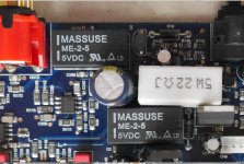
After modification of R140: into 22 Ohm 5W instead of 62 Ohm 2W and change of C270 to a good quality Panasonic FC series (105 deg. C) 470uF 63V, I have had No problems anymore with the muting circuit;
So: That problem was solved!
3)
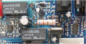
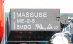
The Massuse ME-2-5 relays are not very good quality either, IMO;
I bought equivalent FINDER Relays 30.22.7.005.0010, which have gold plated contacts and are fully fluid tight.
That was a planned upgrade; but this was not necessary, yet.
4)
I posed the same question on the Dutch Forum : Circuits On Line and apart from suggesting to leave the design As-Is (albeit with much better quality Electrolytic capacitors, preferably Hi temp ones), as you recommended,
it was also felt that the swap of 10uF 50V Electrolytic capacitors to 2.2 uF or 3.3 uF film capacitors, would do no harm.
If the AZUR 840C would break down again, I will follow that route to eliminate that heat problem and resulting deteriorating electrolytic capacitors Once and for ALL!
Thanks again!
1)
Sorry Mooly : Slip of the pen; :
My Mains voltage varies between 229 Volts AC and 230 Volt AC, 50 Hz. (so quite a good performance from the Electricity Co.).
Sorry for having put you on the wrong foot.
Obviously not 290V otherwise all my electronic equipment would have blown up!!
The nominal design voltage of the AZUR 840C is 230V AC .
(Here in the Netherlands, we used to have 220 V AC, in the UK 240V AC , but we were forced to adapt to to the Brits, so indeed once has to be careful with older equipment.
2)
The 3 muting Relays are directly fed from a Graetz rectifiying bridge and a 2 x 2200uF V 50VF capacitor (10V unregulated) and are therefore dependant on fluctuations in the mains voltage, but these are negligible, in my case.
After modification of R140: into 22 Ohm 5W instead of 62 Ohm 2W and change of C270 to a good quality Panasonic FC series (105 deg. C) 470uF 63V, I have had No problems anymore with the muting circuit;
So: That problem was solved!
3)
The Massuse ME-2-5 relays are not very good quality either, IMO;
I bought equivalent FINDER Relays 30.22.7.005.0010, which have gold plated contacts and are fully fluid tight.
That was a planned upgrade; but this was not necessary, yet.
4)
I posed the same question on the Dutch Forum : Circuits On Line and apart from suggesting to leave the design As-Is (albeit with much better quality Electrolytic capacitors, preferably Hi temp ones), as you recommended,
it was also felt that the swap of 10uF 50V Electrolytic capacitors to 2.2 uF or 3.3 uF film capacitors, would do no harm.
If the AZUR 840C would break down again, I will follow that route to eliminate that heat problem and resulting deteriorating electrolytic capacitors Once and for ALL!
Thanks again!
Attachments

Hi Mooly,
I'm not hellbent on using film capacitors, but it is for me (as an amateur with limited tools) the only practical solution to replace all those little 10uF 35V capacitors.
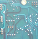
I am dealing with a double sided PCB with very small ID , vulnerable metallic feedthroughs.'
So unlike old-fashioned PCB's it is very difficult to replace all those caps without ruining the board and thus create a Total Write Off.
The most practical approach for me is to cut off the Electrolytic capacitors at the top side of the board (maintaining the feedthroughs) and to solder the replacement filmcaps at the bottom side of the board .
For the time being, the AZUR 840C CD player / DAC is working splendidly, but if the need would arise, the above approach will be my repair strategy, for pragmatic reasons.
I will check with an analogue scope, whether there are no oscillations or ripples on those power lines.
One has to be practical to get to a workable solution. It is not an academic study!
Again many thanks for your extensive advice!
I'm not hellbent on using film capacitors, but it is for me (as an amateur with limited tools) the only practical solution to replace all those little 10uF 35V capacitors.
I am dealing with a double sided PCB with very small ID , vulnerable metallic feedthroughs.'
So unlike old-fashioned PCB's it is very difficult to replace all those caps without ruining the board and thus create a Total Write Off.
The most practical approach for me is to cut off the Electrolytic capacitors at the top side of the board (maintaining the feedthroughs) and to solder the replacement filmcaps at the bottom side of the board .
For the time being, the AZUR 840C CD player / DAC is working splendidly, but if the need would arise, the above approach will be my repair strategy, for pragmatic reasons.
I will check with an analogue scope, whether there are no oscillations or ripples on those power lines.
One has to be practical to get to a workable solution. It is not an academic study!
Again many thanks for your extensive advice!
One way to deal with plated through vias is to snip the part as you say, then heat and at the same time pull each remaining lead out. To clear the hole use stainless wire, the solder wont stick to that but its messy to do.
Ideally any work done should look indistinguishable from a factory job. That's always a big thing for me, it has to look good as well.
Caps that haven't suffered with heat should really be fine so perhaps no need to change them all.
Ideally any work done should look indistinguishable from a factory job. That's always a big thing for me, it has to look good as well.
Caps that haven't suffered with heat should really be fine so perhaps no need to change them all.
Hi Mooly,
Thanks for the advice on the use of a stainless steel wire, to clear the holes.
(I use the same procedure for single sided PCB boards from the 1970's ( I use a worn jeweller's screwdriver (smallest size of the set) to clear the holes).
Thereafter, it is very easy to install new parts (mostly Electrolytic Caps or transistors).
However, this 2008 Cambridge AZUR Board uses 3 layer PCB technology, so it is very important not to wreck those feed troughs (it is impossible to resolder the middle ones).
Hence, my plan to leave the existing interconnects from the old caps in-situ and replace the replacement caps lying flat on the bottom side of the PCB.
There is enough room, so no sweat.
For me the original look is not important as long as the repair is done neatly.
Once the PCB has been installed again, those C's are not visible anyhow and moreover they are now better screened by the bottom plate of the housing.
Cheers and many thanks! Martin
Attachments
Mooly,
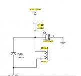
If I may, I would like to revisit your comment in your post of yesterday 10:14 AM , regarding the activation of the 3 Mute Relays RL-1, -2 and -3 by R140 and C270. from a 10V DC line.
AA)
In the AZUR 740C 1 Relay is used, R140=62 Ohm, C5 =470 uF , Vunregulated = 10V
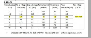
(The nominal voltage of the Relay coil = 5V, it's nominal current =40 mA, Coil resistance = 125 Ohm)
Hence, in the AZUR 740C in Steady State conditions the coil current is ~50 mA which is 1.25 Times the nominal coil current of 40 mA (which seems to be All Right).
BB)
In the AZUR 840C three relais coils are wired in parallel.
However R140 is still 62 Ohm and C270 470 uF.
I reasoned that at Steady State conditions the 3 Relays now receive 96 mA (32 mA per relay) which is lower than the nominal 40 mA per relay.
Thus I changed R140 to 22 Ohm : now the relay coils receive 157 mA total in Steady State conditions (which is 52 mA per Relay again 25% higher than the nominal current (per relay coil of 40 mA).
(Of course this is assuming that the total current is equally distributed across the 3 relays coils, which might not be correct).
I have kept C270 on 470 uF.
Observation: The relays now switch more firmly than hitherro (which is good).
Hence, I thought that I had solved the erratic mute relay problem,
Unfortunately I have observed that if I switch the 840C CD player / DAC ON ("cold boot") with the "Master" power switch at the back, that sometimes one contact (channel) of RL3 does not always close (after I have subsequently switched the 840C fully ON with the Standby switch at the front).
This occurs if I do NOT wait not long enough ( < 20 seconds) between activating the "Master" power switch at the back and activating the "Standby switch" at the front.
(NB The operating manual specifies that the On/Off switch at the back should always be ON, (this activates a 5V DC supply permanently and a PIC in the front panel (so IMO not so desirable in view of wear and tear)).
Now my question:
Would the erratic operation of RL3 for short times between activation of the "Master" On/Off switch at the back and the "Stand By "switch at the front (despite correct dimensioning of R140 to 22 OHM) be attributable to C270 which might also be incorrectly sized for 3 relays?
If so, could you please advise , how C270 should be adapted (e.g. should the capacity perhaps need to be increased to 1500 uF) ??
Your opinion/guidance would be highly appreciated!
Please note that if I keep the Master switch ON at all times, this problem does not seem to occur!
However, I prefer to switch te equipment fully OFF (in view of Wear and Tear and Safety (fire risks).
Thanks for your opinion.
Regards, Martin
I think that this is quite a fundamental question since the Cambridge Co was also struggling with this very same problem (see Service Bulletin Attached) and might not have discovered the entire root cause (except a poor quality Cap C270).
If I may, I would like to revisit your comment in your post of yesterday 10:14 AM , regarding the activation of the 3 Mute Relays RL-1, -2 and -3 by R140 and C270. from a 10V DC line.
AA)
In the AZUR 740C 1 Relay is used, R140=62 Ohm, C5 =470 uF , Vunregulated = 10V
(The nominal voltage of the Relay coil = 5V, it's nominal current =40 mA, Coil resistance = 125 Ohm)
Hence, in the AZUR 740C in Steady State conditions the coil current is ~50 mA which is 1.25 Times the nominal coil current of 40 mA (which seems to be All Right).
BB)
In the AZUR 840C three relais coils are wired in parallel.
However R140 is still 62 Ohm and C270 470 uF.
I reasoned that at Steady State conditions the 3 Relays now receive 96 mA (32 mA per relay) which is lower than the nominal 40 mA per relay.
Thus I changed R140 to 22 Ohm : now the relay coils receive 157 mA total in Steady State conditions (which is 52 mA per Relay again 25% higher than the nominal current (per relay coil of 40 mA).
(Of course this is assuming that the total current is equally distributed across the 3 relays coils, which might not be correct).
I have kept C270 on 470 uF.
Observation: The relays now switch more firmly than hitherro (which is good).
Hence, I thought that I had solved the erratic mute relay problem,
Unfortunately I have observed that if I switch the 840C CD player / DAC ON ("cold boot") with the "Master" power switch at the back, that sometimes one contact (channel) of RL3 does not always close (after I have subsequently switched the 840C fully ON with the Standby switch at the front).
This occurs if I do NOT wait not long enough ( < 20 seconds) between activating the "Master" power switch at the back and activating the "Standby switch" at the front.
(NB The operating manual specifies that the On/Off switch at the back should always be ON, (this activates a 5V DC supply permanently and a PIC in the front panel (so IMO not so desirable in view of wear and tear)).
Now my question:
Would the erratic operation of RL3 for short times between activation of the "Master" On/Off switch at the back and the "Stand By "switch at the front (despite correct dimensioning of R140 to 22 OHM) be attributable to C270 which might also be incorrectly sized for 3 relays?
If so, could you please advise , how C270 should be adapted (e.g. should the capacity perhaps need to be increased to 1500 uF) ??
Your opinion/guidance would be highly appreciated!
Please note that if I keep the Master switch ON at all times, this problem does not seem to occur!
However, I prefer to switch te equipment fully OFF (in view of Wear and Tear and Safety (fire risks).
Thanks for your opinion.
Regards, Martin
I think that this is quite a fundamental question since the Cambridge Co was also struggling with this very same problem (see Service Bulletin Attached) and might not have discovered the entire root cause (except a poor quality Cap C270).
Attachments

It is hard to say for sure what is happening.
One possibility is that the actual relay contact isn't great in itself and that particular problem is masked by getting the relay to snap shut with force by means of the cap providing a sudden pulse of the full 10 volts.
The physical force of the fast moving contact may be masking the real problem of a dodgy/poor relay.
In other words if you take a good relay and very slowly ramp up the coil voltage then at some point the contact will very lazily move over and the contact should be electrically good.
If the contact is tarnished or poor then the electrical contact may be intermittent.
Now if we close the relay very quickly with a high voltage pulse the mechanical shock may appear to 'fix' the poor contact issue each time it operates.
So all that is one very real possibility.
The cap can be increased drastically I would say. It can not load the rail much during charging because of the resistor. 1500uF, even 2200uF should all be absolutely fine imo.
Good morning Mooly,
Many thanks for your fast reply!
You indeed confirmed my own thoughts / suspicions regarding this issue.
(For that reason, I had already bought as replacement, 3 Finder relays with exactly the same electrical spec's, but having an improved mechanical construction (Gold plated contacts, hermetically sealed); Type FINDER 30.22.7.005, in lieu of the existing Massuse ME2-5.
So all in all, it was a shame that Cambridge spoiled a very nice CD/DAC player by inferior components (electrolytic capacitors, relays), especially since it was at the time quite an expensive device .
Whilst I type this, I listen to a nice 24/192 HiRes Download, played via the DAC of the AZUR 840C .
The sound is very nice (at the time it got rave reviews), so I will hold on to it and if need be, I will change out all those dodgy Electrolytic Capacitorsa and the muting Relay RL3 (I do not use the XLR outputs, hence do not use RL1 and RL2).
Many thanks again for all your explanations/diagnosis ( a steep learning curve for an amateur such as me).
All the Best! Martin
Attachments
- Status
- This old topic is closed. If you want to reopen this topic, contact a moderator using the "Report Post" button.
- Home
- Source & Line
- Digital Source
- Film capacitors i.o.f Electrolytics icm LM78xx regulators: Minimum Value required?