I have question for anyone willing to help:
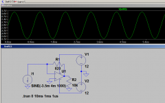
I need to end the Iout of a DAC into roughly a 1.8v potential caused by 3 BE junctions as part of the input of an I/V converter .Would a ground lifting done with 3 diodes (or a green LED or just other 3 BE junctions paralleled with some capacitors work?
I need to end the Iout of a DAC into roughly a 1.8v potential caused by 3 BE junctions as part of the input of an I/V converter .Would a ground lifting done with 3 diodes (or a green LED or just other 3 BE junctions paralleled with some capacitors work?
Attachments
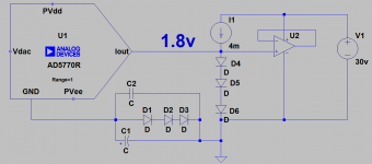
You need to revisit that circuit, you don't have an I/V converter at all, and the diodes short the output of the dac through their dynamic resistance directly to ground.
Connect I/V converter to inverting input of opamp, add resistor between inverting input and output to set the I/V ratio.
Connect your 1.8V reference directly to the op-amp non-inverting input.
I don't understand why you have diodes in series with the gnd pin of the DAC chip, this shifts a whole lot of things inside the chip away from ground and adds the dynamic resistance in series with all the of dac current.
Perhaps you tell us what you are trying to do?
Interesting indeed that I myself, for the first time built a 'ground lifter' for my DAC only a couple of days ago, so I can see the intent even though the circuit isn't drawn up correctly. You need to get the output voltage of the DAC to be both within its allowed compliance range AND compatible with the I/V opamp, which means roughly mid-rail. I used a TL431 to give a 2.5V lift to my DAC, rather than diodes.
The drawback is we now need level shifters to put the DAC's digital input signals into the right range. Fortunately that's not very hard to do - I use current sources and voltage references (TL431s).
The drawback is we now need level shifters to put the DAC's digital input signals into the right range. Fortunately that's not very hard to do - I use current sources and voltage references (TL431s).
I'm sorry for the sloppy figuration of a different circuit actually! I'm still working on it. I don't have a conventional virtual ground circuit...You need to revisit that circuit, you don't have an I/V converter at all, ...................
Last edited:
Thank'you! I'm using completely different ground planes coming from different power supplies .I'll be using PCM1798 or 1794 as dac so i'll need to use its Vcom or I ref...I don't really know how i'll be using them .I just found out that i also need variable ground lifting too ...Interesting indeed that I myself, for the first time built a 'ground lifter' for my DAC only a couple of days ago, so I can see the intent even though the circuit isn't drawn up correctly. You need to get the output voltage of the DAC to be both within its allowed compliance range AND compatible with the I/V opamp, which means roughly mid-rail. I used a TL431 to give a 2.5V lift to my DAC, rather than diodes.
The drawback is we now need level shifters to put the DAC's digital input signals into the right range. Fortunately that's not very hard to do - I use current sources and voltage references (TL431s).
Last edited:
In a typical case, the opamp is going to be fed from balanced (+/-) supplies and the DAC will be referenced to 0V so this issue doesn't arise. In my case though, as I'm using a single supply, the 0V is where the -ve supply would normally be and then to avoid using a coupling cap into the I/V we become limited in the supply the opamp can run from in order to keep the mid-rail voltage within the DAC's compliance range. Raising the DAC's 0V gives much more flexibility in choosing the supply rails of the opamps.
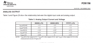
In the end i chose to lift the i/v converter ground , but i don't really understand the pcm179x line.Because i intended to use pcm1798 , i need to refer to this table , but then, i don't understand why Vcom and Iref are 2.3 and 2.4v while the swing center is -2.87v...Which one should i use for reference for my ground drive?
Attachments
@dreamth:
Hi ... I think you can consider the specifications as if they are seen from the output of the Iout+/- of the PCM179* DAC. That is: The DAC output outputs/sends out a center current of 3.5mA (the minus is because it is output from the Iout pin) and because it is a negative current (coming out of the Iout pin) the voltages may also be negative (U=R*I, and with a negative current it gives a negative voltage) when referencing the Iout pin.
However, I assume that the output of the PCM1798 should not be at a negative voltage relative to the DAC's power supply ground. I again assume that this may damage the DAC's outputs (others may know more about this though).
There's a thread here on diyaudio where testing was done on the PCM1794:
Testing the pcm1794
and I reckon the PCM1798 has a similar - although not identical - output stage. As you can see in this thread when lifting the output pins' reference voltage level above what an appr. 50 ohm resistor gives, the distortion starts increasing. If the output BPZ current is 6.2 mA - as it is for the PCM1794 in a standard configuration - this means keeping the output reference level below ~0.3 volts.
Both the PCM1798 and PCM1794 are supplied from +5V & +3.3V supplies (I may, however, suggest that you take a look at the DDDAC in this context).
I hope this may be of help.
Best regards,
Jesper
Thanks! I remember seeing this topic before, but not reading it in depth.Then may I assume that the output is actually ground centered , just the output swing is asymmetrical on each output relative to ground, but both outputs make a symmetrical signal ?@dreamth:
Hi ... I think you can consider the specifications as if they are seen from the output of the Iout+/- of the PCM179* DAC. That is: The DAC output outputs/sends out a center current of 3.5mA (the minus is because it is output from the Iout pin) and because it is a negative current (coming out of the Iout pin) the voltages may also be negative (U=R*I, and with a negative current it gives a negative voltage) when referencing the Iout pin.
However, I assume that the output of the PCM1798 should not be at a negative voltage relative to the DAC's power supply ground. I again assume that this may damage the DAC's outputs (others may know more about this though).
There's a thread here on diyaudio where testing was done on the PCM1794:
Testing the pcm1794
and I reckon the PCM1798 has a similar - although not identical - output stage. As you can see in this thread when lifting the output pins' reference voltage level above what an appr. 50 ohm resistor gives, the distortion starts increasing. If the output BPZ current is 6.2 mA - as it is for the PCM1794 in a standard configuration - this means keeping the output reference level below ~0.3 volts.
Both the PCM1798 and PCM1794 are supplied from +5V & +3.3V supplies (I may, however, suggest that you take a look at the DDDAC in this context).
I hope this may be of help.
Best regards,
Jesper
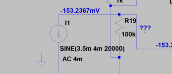
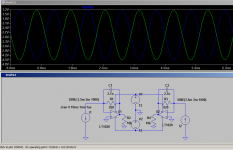
I think these two simulation sources show how we should think about this dac line:
https://www.diyaudio.com/forums/digital-source/221743-testing-pcm1794-10.html#post4057376
Website of Wayne Stegall - DAC Cascode - Analog DAC circuit designed with one BJT
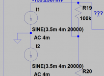
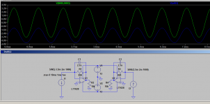
Yet, if want to sim a fully balanced i out source then i get in real trouble because i don't know how to sim a balanced mode pcm1798/94.Should I define the PCM1798 current source as in the first photo or do i need to actually define 2 current sources referenced to earth instead , each of them with its own current offset?
https://www.diyaudio.com/forums/digital-source/221743-testing-pcm1794-10.html#post4057376
Website of Wayne Stegall - DAC Cascode - Analog DAC circuit designed with one BJT
Yet, if want to sim a fully balanced i out source then i get in real trouble because i don't know how to sim a balanced mode pcm1798/94.Should I define the PCM1798 current source as in the first photo or do i need to actually define 2 current sources referenced to earth instead , each of them with its own current offset?
Attachments
Last edited:
Ok...so i had to measure myself the PCM1798 dac on the real board of my Audient ID22 again.
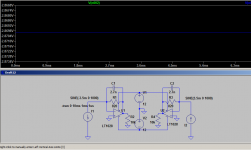
Actually there's a real -3.5ma of DC offset on both outputs related to ground as the DC voltage output on the I/V op-amp(NJM8080) is -2.76...-2.78v (real values ) with a 820...822ohm feedback resistor. So this is how i figured out to sim this dac in balanced mode cause otherwise i'll never finish my I/V stage....
Actually there's a real -3.5ma of DC offset on both outputs related to ground as the DC voltage output on the I/V op-amp(NJM8080) is -2.76...-2.78v (real values ) with a 820...822ohm feedback resistor. So this is how i figured out to sim this dac in balanced mode cause otherwise i'll never finish my I/V stage....
Attachments
Last edited:
@dreamth: Hi again ... Hmmm ... maybe there's a misunderstanding here: I thought that you were talking about having a negative voltage on the output pin of the PCM1798 - not on the output of the opamp actually making the I/V conversion. But, yes, it would seem that with the configuration you've drawn up there would be somewhat - 2.87 VDC on the output of the opamp. And there will be appr. 0 volt on the inverting input of the opamp.
In my simulations of the PCM1794 I have added a 2 Mohm resistor from the current output of the current sources (I- and I+ from the PCM1794) to ground ... However, in your setup where the input impedance of the opamp is very low these additional two resistors will not really make a difference.
Good luck with your I/V stage endeavors!
Regards,
Jesper
Thanks! Solved now...@dreamth: Hi again ...
Good luck with your I/V stage endeavors!
Regards,
Jesper
PCM179x DAC converter to electrostatic headphones output
- Status
- This old topic is closed. If you want to reopen this topic, contact a moderator using the "Report Post" button.
- Home
- Source & Line
- Digital Source
- Ground lifting dac-i/v