Hi Chris,
Got back from my father’s 73 B-day party a little while ago. Thank you for taking the time to think about this!
The speck is small which is why I didn't notice it. I don't know if it really is the culprit but it is the only thing I've found of potential interest and figured I had better mention it. I have been over the board completely about 4 times now and see nothing. I only messed with a small section and 100% sure nothing there.
The current status of the player: Laser assembly disconnected at Header CN101. Analog process board removed. Remote control board removed. Everything else is connected.
I honestly thought I was posting info on those circuits that might be related and useful. Clearly I'm not posting useful information which I am sorry for.
I thought the Voltages I was seeing weren't supposed to be there since the Schematic seemed to indicate they shouldn't be and so I posted this info thinking it would be diagnostic.
I know better than to turn any VR and have not.
I cannot find anything wrong with the Flex cable and if it cracked somehow I can't tell under magnification. The flex cable was only removed after the ANTISTAT solder was in place and with the unit off.
Is there some way to test the diodes out of player and in a safe non-destructive way?
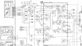
I posted the Power supply section in post 1. I am only seeing one fuse symbol in the primary of the transformer.
I'm guessing the unit uses resistors as fuses but not sure which ones and they are not labeled as such. I have seen in amps where they are labeled FR and some number. The FR standing for Fuse Resistor.
In the above post I included R802 and R803 before and after voltages thinking those maybe fuse resistors.
I will post some more scans of the Schematic and if you would like I can send you the entire scan in a PM or something, but unfortunately I won’t be able to try anything else for a few days but am absolutely willing to continue when I am able next week.
Chris thank you for taking the time to help it really is amazing and you are truly kind to do it. With any of this stuff time takes its toll and I thought I would at least try to save this unit from the rot but may have inadvertently killed it and I won’t lose sleep over it if I did.
This was a great player, although sort of a curiosity, and it would seem that the laser assembly is not common and that alone makes this player destined for recycling when it goes dead. If it really is done for there are some useful parts most notably the TDA1541A S1.
I’ll keep looking and if there is any info that would help that I can provide I will!
Thank you so much,
Mark K.
Got back from my father’s 73 B-day party a little while ago. Thank you for taking the time to think about this!
The speck is small which is why I didn't notice it. I don't know if it really is the culprit but it is the only thing I've found of potential interest and figured I had better mention it. I have been over the board completely about 4 times now and see nothing. I only messed with a small section and 100% sure nothing there.
The current status of the player: Laser assembly disconnected at Header CN101. Analog process board removed. Remote control board removed. Everything else is connected.
I honestly thought I was posting info on those circuits that might be related and useful. Clearly I'm not posting useful information which I am sorry for.
I thought the Voltages I was seeing weren't supposed to be there since the Schematic seemed to indicate they shouldn't be and so I posted this info thinking it would be diagnostic.
I know better than to turn any VR and have not.
I cannot find anything wrong with the Flex cable and if it cracked somehow I can't tell under magnification. The flex cable was only removed after the ANTISTAT solder was in place and with the unit off.
Is there some way to test the diodes out of player and in a safe non-destructive way?
I posted the Power supply section in post 1. I am only seeing one fuse symbol in the primary of the transformer.
I'm guessing the unit uses resistors as fuses but not sure which ones and they are not labeled as such. I have seen in amps where they are labeled FR and some number. The FR standing for Fuse Resistor.
In the above post I included R802 and R803 before and after voltages thinking those maybe fuse resistors.
I will post some more scans of the Schematic and if you would like I can send you the entire scan in a PM or something, but unfortunately I won’t be able to try anything else for a few days but am absolutely willing to continue when I am able next week.
Chris thank you for taking the time to help it really is amazing and you are truly kind to do it. With any of this stuff time takes its toll and I thought I would at least try to save this unit from the rot but may have inadvertently killed it and I won’t lose sleep over it if I did.
This was a great player, although sort of a curiosity, and it would seem that the laser assembly is not common and that alone makes this player destined for recycling when it goes dead. If it really is done for there are some useful parts most notably the TDA1541A S1.
I’ll keep looking and if there is any info that would help that I can provide I will!
Thank you so much,
Mark K.
Attachments
Chris I really hope your dog is well and everything goes ok! We have 3 golden retrievers and they are precious so please don't worry about this in any way. I won't be around for a few days so honestly there is no reason to get on this right now and I am not in a hurry.
Thank you,
Mark K.
Thank you,
Mark K.
Hi Mark,
We have a Standard Poodle, a type called a Silver Poodle (we call Sterling). His hair started out jet black and is turning the colour of his face (white-grey). He always had a white face, which looked pretty cool. The summer before last we had to put another Standard Poodle, Mr Darcy, down at 10 1/2 years due to bloat. There was no way I was going to lose another dog who is only 15 months old now. I don't know how we'll pay the vet bill, but we will work that out best we can later. Two summers before Mr. Darcy died, we lost another Standard Poodle named Remy, but that was mostly old age. He was a King Poodle, pretty tall. I would love another Poodle to keep Mr. Sterling busy doing dog things. Otherwise, we are his only source of entertainment. Poodles do have a sense of humor!
-Chris
Hi Mark,
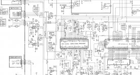
Okay, to understand the focus circuit, have a look at the pick-up diodes in the square (A, B, C and D). This is your signal source that generates almost everything you need except for the E and F diodes that the tracking servo uses. We can ignore those for now. So, looking at the connections for the A and C diodes, we see they are shorted together, as are diodes B and D. When the laser is centered, or focused on the CD, the outputs from these combinations is equal. As the lens moves away from the CD's surface, the spot becomes sort of like an ellipse that moves so that one set of diodes has more output than the other. This becomes the focus error signal and is filtered so that the low frequency components are processed to generate the Focus error signal that is applied to the servos. The analogue processor (IC101 inputs a current into the focus loop that works with the capacitor to generate a ramp signal that allows it to do a focus search. If it finds the CD surface on the information layer, the servo locks and the Fok line changes state. This shuts down the focus search current injection and allows the disc to spin up to speed.
The higher frequency components of the signal are filtered out and processed by the analogue processor a little differently. This signal becomes the RF signal which is further processed to become the EFM signal. From this, we extract the digital information, and also the clock. The clock signal is compared to the VCO on board and the difference between them provides the spindle (disc) motor drive. When the difference is about 50%, the motor and clock are locked up, and this allows the speed to be controlled so you get a valid data stream that doesn't underflow or overflow the FIFO memory. The data is clocked out by the system reference clock, so you get very little jitter or wow and flutter. The CD will spin close to 500 rpm in the middle (starting tracks) and it will drop slowly as you reach the outer edge to about 200 RPM depending on how much information there is on that disc. I think 74 minutes is the official limit.
Now you can see (except for the tracking servo) how the CD is locked up and information is extracted. The focus servo compares the focus signal DC level to a reference level (focus offset control) and from that generates a correction to raise or lower the lens. All these servos have a time constant to reduce extraneous noise (like the higher frequency information for example). So the signal must remain within the bounds set by the time constants. Everything outside of that has reduced amplitudes.
Thinking about how the focus search is done, it sounds as if the capacitor they use to generate the ramp isn't there, or is the wrong value. By wrong value, I mean greatly reduced from its proper value. The servo can't lock to the equilibrium state between the diodes, so the lens remains at it's limit of travel until the next search (normally three attempts). But the focus search feature is turned of and the capacitor discharged quickly, then another pulse arrives to start the ramp - which just pegs the lens again. It may look like it pegs and stays there. So I would check that capacitor. the Fok signal is on pin 28 and also a s test point maybe. Your focus error (FE) is output on pin 19. IF you look at pins 7 and 8, you'll see they go to transconductance amplifiers so that the current signal is converted to a voltage needed by the system to process. It doesn't show the current injection point for the focus search (which I was hoping to find for you).
Just for interest, the RF signal is what we normally look at to see the overall health of the system. It gives you a wealth of information about the CD player, kind of like a blood test. What you want to see is a stable eye pattern with clear eye openings with low noise.
The head in this player is a Pioneer head I think. So easy to find on the net. It isn't a rare head at all. So this player is well worth fixing.
-Chris
Hi Chris,
First off I can't thank you enough! I don't have a lot of time and this will be my last post for a few days.
I sincerely hope Sterling does well and lives a long happy life. I have had dogs around me my whole life mostly Goldens but a couple of labs and one poodle terrier mix named Muffin. He was a character and a half. He was also an amazing rodent catcher! They have all had their own characters. Our old timer Woodrow is 12 yrs old and a few years ago we got two sisters for him Penny and Poppy! Couldn't live without them in our lives.
I will digest what you have written and again thank your for taking the time and explaining it clearly. I think I am actually am getting it. I won't be able to do more measuring for a few days. Sorry for this. I am eager to find the issue though and maybe there is hope for this player. Gonna keep a positive outlook till the end!
Sincerely take care and thank you,
Mark K.
Hi Mark,
No problem.
Thank you, Sterling is doing well. He tolerated the procedure very well I'm told. So I took him out and got him a couple "Tim Bits". He gets to go back to the dog park later on today, so he really is out of the woods completely.
Talk to you in a couple days or so Mark.
-Chris
No problem.
Thank you, Sterling is doing well. He tolerated the procedure very well I'm told. So I took him out and got him a couple "Tim Bits". He gets to go back to the dog park later on today, so he really is out of the woods completely.
Talk to you in a couple days or so Mark.
-Chris
This thread reminds me of the great times when Chris / anatech helped me with his patience and detailed explanations in setting up my Nakamichi OMS-5II player! (Still up and running btw).
Mark, when you are further interested interested in repairing a CD-Player,
I strongly recomment this book by Ken Clements:
"Understanding and Servicing CD-Players"
It does not only give basic Information on how they work. As Sony and Philips were the
market leaders (selling their parts to other companies like Nakamichi)
there are also understandable circuit descriptions based on the Sony and Philips chipsets.
The same chipsets were used in three to four generations of Players so the book describes
more than a decade of development, it think it was issued around 1993
I only read quickly over your discussion but I remember that a blown fuse-resistor
triggered the same behaviour (lens kicking in one direction) in a used Nakamichi OMS-7II I bought.
(This Nak is Sony based). But yours seem to work, correct?
All the best,
Salar
Last edited:
Hi Chris, "nuttyness" (don't know whether this
word exists) starts to slow down here. 6 weeks of
fixing corrupt CAD data for my CD-Player prototpe
will end today. I am waiting for the third attempt to
anodize the surface of a sample in a glass bead blasted
shiny look to be done properly - also a mever ending
story...
Coming back to the fuse resistors of Mark's Nak:
Could it be that they became high resistant
but still still show the correct voltage under
the non existant load of a voltmeter?
Can't be, correct?
All the best, Salar
Hi Salar,
For me, it's been a stream of really tough repairs that others have attempted previously. Those attempts may have been years earlier in time, but they are finally breaking down. Trying to decipher what someone else did before can be a frustrating task. I have to keep reminding myself to start looking in the most basic places, and I'm often disappointed when I look there.
The worst jobs seem to be done by members of Audio Karma, and those are looking good compared to the idiots who get their information off the internet and buy "kits" to "fully repair and upgrade" whatever the unit is. Many have such poor soldering skills that they damage the PCB. Using "hobby irons" they can damage ICs and even transistors from the leakage current these devices can generate. Nothing dramatic like a big spark (I wish they would), just something like it worked before replacing capacitors, and now it doesn't. That and selling on various web sites as "recapped". That should be code for "it's been buggered up". Someone having done a hundred of these jobs does not make them skilled at anything more than talking people into jobs.
My favorite was a comment made by one of these internet hackers that claimed that rebuilding these by a real technician shouldn't cost more than $375 (US). I'm sure that orator claims he is highly trained while having no idea what else need to be done, or even the proper technique for doing what he hacked in there. I highly doubt if he even has the most basic instruments.
Recently a Marantz 300DC came in just done by another technician. This guy claims he is an expert (without any formal training), but he took over the family business, a repair shop. When the amplifier was checked, one channel completely failed it's performance test for THD. Looking in further, he had replaced the outputs "because they were leaky" with "matched outputs". The original transistors were not only fine (no leakage), they were more closely matched than the ones he installed. Otherwise his work was very clean - no complaints. He just needs education. He is skilled at separating people from their money and installing unnecessary parts. Now I'm trying to track down the cause for the very high distortion. He should never have released the amp with that high distortion level, but he probably doesn't have a THD meter. He did say he uses his sound card. Probably an AK member held in high esteem. I did call him after exchanging email. He was extremely hostile and unwilling to accept any form of help. He didn't even want to use the transistor matcher I was going to give him. IT was depressing to see someone who was good at the mechanical aspects of the job, and trying to do good work (by his claim) who refused any form of information to help him do a better job. As a result, I cannot send him work when I'm overloaded.
Sorry, fresh issue that I had to get off my chest.
-Chris
Hi Salar,
To answer your query, he measured the resistance / continuity of those devices. You're right about a higher load (just a meter) might allow some current to flow. But most people test in circuit with the normal load still connected. Those fuse resistors tend to look perfectly fine while being open. Even normal resistors can open without looking burned out and the only visual sign would be a small burned dot on the side of the resistor facing the PCB. Nice! Those are difficult to find, especially when the load they supply has other current paths to the supply. That can make them measure something, normally too high.
The worst ones to find are those semi-fuses that look like small signal transistors, but with only two leads. Vari-cap diodes and diacs look the same, a signal transistor case with only two leads. I have seen specialty diodes that also look like this.
With surface mount components, things are even worse as diodes are often in a SOT23 case that are absolutely identical to a transistor. I'm pretty sure there are other cases that also house diodes and other parts instead of a transistor. The number printed on the case may not help without the service manual.
-Chris
Well, earlier times it was nostalgia but it becomes more and mor proven that
many vintage gear outperforms modern one. So it is sad to hear when People spoil
it. BTW, a Yamaha A1 was recently measured/tested at audiosciencereview.com
and still performs very well:
Yamaha A-1 Vintage Amplifier Review | Audio Science Review (ASR) Forum
But now back to topic...
many vintage gear outperforms modern one. So it is sad to hear when People spoil
it. BTW, a Yamaha A1 was recently measured/tested at audiosciencereview.com
and still performs very well:
Yamaha A-1 Vintage Amplifier Review | Audio Science Review (ASR) Forum
But now back to topic...
")
Hi Chris,
Just getting home and pretty tired now.
I am relieved to hear Sterling is well!
I will do some more exploration tomorrow.
Hi Salar,
Thank you for coming in and I have lurked on some of your threads! I appreciate the info on the literature! I have a large collection books and find printed works invaluable, so I will more than likely now buy Ken's book. I also try to acquire every manual I can for everything I own not just audio related, just so I have the reference if needed.
Thanks guys,
Mark K.
Last edited:
Well- hope we will do our parts some day in saving some of those Players...
Mark, I am missing in the drawings scans the circuitry leading to the focus coil.
There should be some transistors involved, shouldn´t they?
Hi Salar,
Below is a link to a scan I posted in Post 1. I believe the focus coil(CN-101(2/2) pins 16&17), voltage amplifier chip and immediately related circuitry are in this scan. If this isn't what you are asking for I can easily post more scans.
https://www.diyaudio.com/forums/att...s-coil-10v-power-supply-caps-focus-1-copy-jpg
Mark K.
No rush Mark.
Dogs do better than humans do for recovery.
-Chris
Yes they do but I will welcome the day when they might actually tell us what ails them. I hate having to guess when it is serious enough to merit a trip to the vet.
The sisters are trying to establish some sort of pecking order and a couple tussles have occurred lately, nothing serious a little blood on an ear but nerve wracking none the less.
I'm taking it easy with this machine and am encouraged it can be fixed. I took it out of the main system due to having a couple working Philips CDC-875's which uses the same 6 disc cartridge and only one working Nakamichi CDC-4A. I wanted to save the laser for as long as I could by just using it every once in awhile. Then I found the corrosion in the CDC-3A and you know the rest at this point.
I am heading to bed!
Thanks,
Mark K.
Last edited:
Hi Chris and Salar,
I spent some time lifting legs on resistors and some capacitors. Nothing found as of now that has outright failed.
List of tested components:
R101= 46.9 ohms should be 47 ohms
R102= 46.2 ohms should be 47 ohms
R103= 99.79 Kohms should be 100 Kohms
R104= 10.24 Kohms should be 10 Kohms
R105= 8.243 Kohms should be 8.2 Kohms
R106= 2.817 Kohms should be 2.7 Kohms
R107= 56.05 Kohms should be 56 Kohms
R108= 115.9 ohms should be 120 ohms
R110= 3.570 Mohms should be 3.3 Mohms
R112= 988.8 ohms shoud be 1 Kohms
R113= 1.015 Kohms should be 1 Kohms
R114= 12.06 Kohms should be 12 Kohms
R115= 12.03 Kohms should be 12 Kohms
R116= 5.711 Kohms should be 5.6 Kohms
R117= 997.5 ohms should be 1 Kohms
R118= 1.006 Kohms should be 1 Kohms
R119= 5.699 Kohms should be 1 Kohms
R120= 22.36 Kohms should be 22 Kohms
R131= 8.274 Kohms should be 8.2 Kohms
C101= 99.41 uF should be 100 uF
C103= 4744 pF should be 4700 pF
C106= 47.18 uF should be 47 uF
C107= 48.24 uF should be 47 uF
C108= 34.15 nF should be 33 nF
C109= 2704 pF should be 2700 pF
C123= 102 nF should be 100 nF
C124= 105 nF should be 100 nF
C127= 47.44 uF should be 47 uF
C136= 6215 nF should be 4700 nF
C151= 47.14 uF should be 47 uF
C154= 9731 pF should be 10000 pF
C155= 3344 pF should be 3300 pF
C156= 47.22 uF should be 47 uF
Is this pointing towards IC101 or 102 as being the problem?
Thanks,
Mark K.
- Status
- This old topic is closed. If you want to reopen this topic, contact a moderator using the "Report Post" button.
- Home
- Source & Line
- Digital Source
- Nakamichi CDC-4A Laser Focus Coil -10V after new power supply Caps