Looking for expert attention. I will add photos and hard info later.
CDP-30 from thrift store. The manual says KSS-121A but really it's KSS-120C. RF Amp is CX20109, Focus/Tracking/Sled is CX20108, DSP/CLV is CX23035.
Clean, powers up, display bright, laser lights up, seeks and locks focus, spins, locks tracking, but does not lock spindle, and gives up again.
In Test Mode (uC pin 22 grounded), it keeps spinning but still does not lock. Speed goes up and down, never stopping or winding up super fast. MIRR is low (false) with bursts of high. GFS is low (false) with occasional pips.
Objective lens tracks for some seconds then jumps and resumes tracking, so sled is not moving. This may be uC intentional because I know the sled can move - if I mess up E-F balance far enough, the sled wobbles outward or inward on its own.
Initially RF was absent, but I think the sled was hard against the stop due to dirty contacts on the limit switch. With exercise, limit started to close and now when I crank the sled outward by hand then unload/load, it cranks in and stops when limit closes, and we get some RF, presumably the TOC.
RF is weak and (of course) blurry, with dropouts that IIRC are not once per rev but some slower pace, not necessarily regular.
Here's a clue, I think. If I unlock tracking (by grounding TE at RV104 slider), RF increases. A lot. (That is, the maximum increases; minimum is zero as we drift off the pit spiral on every revolution.) Maximum amplitude is a volt-something for sure. When I allow tracking to lock again, RF goes weak again.
What do you think, grating's come loose? (Plus the failure to lock spindle, which might be a separate problem.)
Thanks,
Dave
If you measure the voltage across the sled motor you should see it rise gradually as the tracking error increases, then as the voltage reaches a point the motor can turn the sled will jolt forward a little reducing the error again.
The voltage the motor turns at is normally quite low, a few hundred millivolts or so. If its creeping up higher and the motor doesn't want to turn then the motor or sled may be sticky.
Tracking gain and focus gain are normal not all that critical, at least in an otherwise good player.
Tracking errors should not effect the RF amplitude although the RF will become one horrible noisy mess if the tracking is not locked.
E-F balance and focus bias (if it has that adjustment) are critical.
Itis possible the pickup is faulty, dirty or contaminated internal optics are a distinct possibility on old stuff... the general state of the internals should be a guide here. If its been in a smoky environment then that's not good.
Thanks, Mooly, I will make a point of measuring sled motor voltage. However, the servo chip contains a "sled off" switch which I think is active.
Since I get a reduction in RF when I engage tracking, I am entertaining a hypothesis that my grating is misaligned, which would cause the spot to "track" at a point that's not aligned with the pits.
The player doesn't have any nicotine miasma, but it has been sitting in a dusty place judging from the exterior. Inside the cabinet it's pretty clean. I cleaned the objective lens top surface before starting anyway, but I gather it's possible to clean the bottom too, plus the top of the collimating lens, if I remove the plastic cover. I'll do that unless you start yelling "no!"
This morning I had a few minutes, and I adjusted the VCO free-run. Note: When you undo the board hold-down screws, the cabinet is no longer grounded, so use the board as ground.
The VCO was pretty far off, but I haven't proven that adjusting it helped. I still get weak RF when tracking, and don't read the TOC. I will have to ground TEST MODE to see if I have advanced to CLV lock. I also want to play with my HP 5210A Frequency Discriminator. I ought to be able to put its output on a scope to show the VCO hunt then lock.
It has EF balance (but not tracking offset) and focus bias adjustments. I've adjusted them and ended up near the original set points which were near centered.
I can shore up the grating hypothesis by injecting a tracking offset and see if one way increases RF and the other decreases it.
I'm basing my hypothesis on this old quote:
Pioneer CD Player Grating Adjustment
Comment from edaboard.co.uk by "Mark Z".
++++++++++++++
In test mode, and with the disc spinning, servos open, and observing the HF
pattern, adjust the eye pattern for max, then press the Pause button to
close the tracking servo. If the adjustment is off, the size of the waveform
will drop. Re-adjust a bit to one side or the other until the size of the
waveform is the same whether the servo is closed or not.
This is how the Pioneer guys do it (or did anyway before they all got laid
off).
++++++++++++++
Either he or Sam (of RepairFaq fame) also said that of all the optical pickup failures he'd been through, most were grating come loose and only one or a few were the laser.
Diffraction grating adjustment on those pickups that had that very adjustment was always troublesome, often needing the correct tool. It was virtually impossible to have the pickup playing a disc while at the same time perform the adjustment looking for the numerical 'mid' peak of eight or nine peaks over the full adjustment range.
These are old players now (that chip set was used in the first generation Sony D50 portable). I guess there is nothing lost in delving deeper into the pickup as long as you are careful.
These are old players now (that chip set was used in the first generation Sony D50 portable). I guess there is nothing lost in delving deeper into the pickup as long as you are careful.
I agree, Mooly. Sony never meant their grating to be adjusted in the field. I don't know yet if it's accessible when playing; if not, I figure it's Game Over. I have nothing to lose, the player only cost a few bucks at a thrift store. I'm working on it for fun.
I did see a Russian web page with a drawing of a roll-your-own adjusting tool which fits with Salar's pictures from another thread showing progressive disassembly of a similar pickup. The grating is a disc with a sort of slot on the side, which is visible from the outside through a hole. If you poked in a tool with an eccentric projection and engaged it in the slot, you could cam the grating through a small angle of rotation.
In other news, I'm pretty sure I am getting CLV lock now that I adjusted the VCO. This is the simplest adjustment in this player, you don't even use a disc. Just turn it on, ground TP5 (ASY), measure TP6 (VCO control voltage), and adjust RV106 for 0V. Mine was -0.42 before. Then you put a frequency counter on TP7 (PLCK) and adjust L103 for about 4.22MHz. Mine was 4.0-something before.
Now when I load a disc with TEST grounded so it doesn't give up, the disc spins up then settles at a constant speed, with PLCK wobbling around 4.3-something MHz. I hooked my Frequency Discriminator to PLCK and scoped the output. At rest, the voltage (frequency) is constant. As the disc spins up, it jerks over to another voltage and stays there with random wobbles. At least it looks random until you notice that the major component is repetitive once per revolution. Sounds like lock to me.
When the disc is spinning I can hear bursts of acoustic noise from the focus and/or tracking coils, and some grumbling that I figure is a worn spindle motor bearing. Tonight or at least this weekend, I'll get some scope traces.
I used to have the proper grating adjustment tool for Pioneers many moons ago, it was just a smooth polished shaft of 2 or 3 mm diameter with a circular offset protrusion at the end... pretty much what you describe. It was always bad news when pickups came un-adjusted and was one reason we stopped dealing with them.
I had wrong attribution on a quote. It was David Kuhadja, not Sam or Mark Z, who said that most pickup failures were the grating.
In Notes on the Troubleshooting and Repair of Compact Disc Players and CDROM Drives :
(From: David Kuhajda (dkuhajda@locl.net).)
...
The number one failure I was seeing with optics was not the laser diode output, but from the internal grating lens shifting inside the optics (usually from the glue holding the internal grating lens in place had cracked and come loose).
...
The only case of actual worn out lasers I have seen was in a big box RCA marketed made in China combo stereo. Whenever the unit was plugged in, the laser was on, when the amplifier was turned on the laser would get spiked with large DC voltage.
<end excerpts>
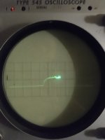
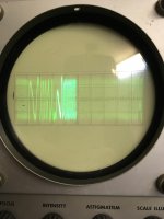
I whipped off some scope traces this morning before work. Didn't have time to check the sled.
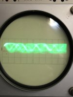
VCO lock-in is obvious. With TP5 ASY grounded, the frequency is 4.22MHz. (I didn't photograph that.) With ASY open and tray open, f is 4.68MHz. With and disc spinning steadily, it's 4.32-4.33MHz. (The discriminator output is inverted.)
The manual's EF Balance procedure just has you open the loop (by grounding the slider of the gain pot) and adjust RV101 for waveform centered on 0V. TE gets smaller when the loop is closed. These traces are unfiltered and polluted with HF content. I'll try again tonight with a LPF in series.
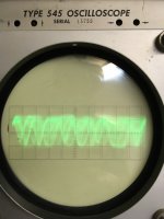
Then I scoped RF, first at a slow sweep to show dropouts, then fast to show we don't get an eye. But note how the amplitude drops when I close the tracking loop. It shouldn't do that, and to the best of my understanding, only a misaligned grating can cause it. Please correct me if there are other suspects.
Thanks,
Dave
I wanted to show the tracking coil voltage ramping up smoothly for some seconds then skipping, but I didn't see it this morning. I'll revisit this weekend.
VCO lock-in is obvious. With TP5 ASY grounded, the frequency is 4.22MHz. (I didn't photograph that.) With ASY open and tray open, f is 4.68MHz. With and disc spinning steadily, it's 4.32-4.33MHz. (The discriminator output is inverted.)
The manual's EF Balance procedure just has you open the loop (by grounding the slider of the gain pot) and adjust RV101 for waveform centered on 0V. TE gets smaller when the loop is closed. These traces are unfiltered and polluted with HF content. I'll try again tonight with a LPF in series.
Then I scoped RF, first at a slow sweep to show dropouts, then fast to show we don't get an eye. But note how the amplitude drops when I close the tracking loop. It shouldn't do that, and to the best of my understanding, only a misaligned grating can cause it. Please correct me if there are other suspects.
Thanks,
Dave
I wanted to show the tracking coil voltage ramping up smoothly for some seconds then skipping, but I didn't see it this morning. I'll revisit this weekend.
Attachments
I think you have probably reached the point where we would say a different pickup should be tried, if only for elimination purposes. As far as I recall when you lower the tracking gain the RF amplitude should remain pretty stable although very blurry when viewed on the scope.
That is what the fault was on my 'KSS 240 restoration' but in this case it was nothing more than a dry on the actual pickup itself.
Sony CDP790 and KSS240 Restoration Project - diyAudio
That is what the fault was on my 'KSS 240 restoration' but in this case it was nothing more than a dry on the actual pickup itself.
Sony CDP790 and KSS240 Restoration Project - diyAudio
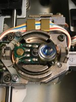
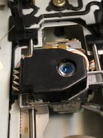
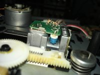
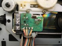
Four more pictures. I reach in with a dental pick to pry off the cover and show what's inside. The collimator lens looked perfectly clean so I didn't try to clean it. No plastic hinges here, it's a voice coil that rotates on a guide pin. The tracking coils are at 2 and 8 o'clock. It's not obvious in the picture but there's a half-covered hole at the bottom of the label that might be grating access. I'll know more when I look at the bottom. If there are tangential and radial adjustments, I figure they're the screws. I'm not getting into that.
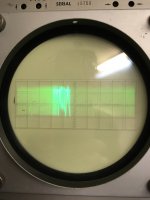
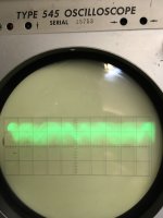
The RF shows just a hint of an eye when it's at its best. I think this model's firmware doesn't hook the sled to TE until the TOC has been read. While looking for TOC, all tracking is handled by the coil - after all, we're supposed to be positioned at TOC anyway, right? (I think the limit switch is dirty and I will look into it. Once in a while we get positioned inwards of the TOC and wind up reading mirror or the human-readable text some pressed CD's have. That stuff really confuses the CLV servo and will overheat the transistors if prolonged.)
While looking for TOC, we track with the tracking coil to the end of servo range, then jump back and start over. As we traverse the range, RF starts out a jumble then gets better and better. (Relatively speaking.) The picture is when it's at its best, right at the end of servo range before it skips back. It is still weak and covered in jitter but you can sort of recognize an eye.
I am more convinced that the grating has rotated. Unless I see how to adjust it, I'm setting this player aside hoping I'll find a pickup someday.
Attachments
That lens arrangement reminds me of the D50 actually.
If so then there could well be a 'rubber band' (some neoprene type material) spring at the rear and that exerts a downward pull on the lens once it is away from its lowest rest point. I once had one where the lens was sticky on that pivot point.
The eye pattern looks just like RF without tracking lock to me... which isn't much help")
If so then there could well be a 'rubber band' (some neoprene type material) spring at the rear and that exerts a downward pull on the lens once it is away from its lowest rest point. I once had one where the lens was sticky on that pivot point.
The eye pattern looks just like RF without tracking lock to me... which isn't much help
The voice coil assembly slides smooth on the guide pin. It looks like gravity is all that pulls it down.
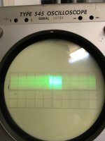
The RF picture looks worse than the human eye and brain see it in person. You really can tell there's an eye, behind all the jitter. I previously attached a picture showing RF with TE open loop. That one's a solid blur; in addition it's almost twice as loud, around 1.7V peak to peak vs 0.7V when locked. You can also tell the difference between music and TOC, the latter looks less cluttered.
It read the TOC successfully once, but it was a fluke.
I'll see if I can get a better picture. I'll get out my camera instead of the phone, and play around with exposure.
More photos and questions.
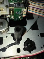
The supposed hole at the bottom of the label turns out to be simply a spot of paint, marking... what? ("Not a Hole.jpg")
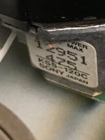
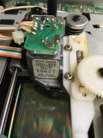
I haven't found a grating adjustment hole, only the grub screw Salar identified as securing the laser diode assembly, which is just visible below the white zip tie securing the LD cable. ("Laser Barrel Grub Screw.jpg")
It's possible it's under the cable strain relief plastic.
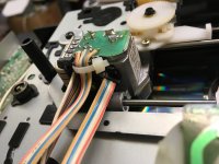
There is, however, another hex-key screw. I don't know if it's for securing or adjustment, but Sony went out of their way to make it accessible, boring a hole in the laser diode junction board to expose it, which suggests it had to be touched with the laser lit up. What could it be? It's along the optical path between the prism and the photodiode array. It's not the grating, that's between the laser diode and the prism, right? ("Optical Path to PDs.jpg" and "Grub Screw or Adjustment Before PhotoDiodes.jpg")
And have you seen crud like this all over the photodiode array board? I don't know if it's conductive, but I'll put on some alcohol and see if it melts. ("Crud on PD Junction Board.jpg")
Finally, notice the machining marks on the PD block. Five projections, three countersunk, one painted black, one untouched. What does it mean? And the hole in the upper left corner of the plate the PD Board is mounted to matches a hole cast into the block. I'd think it's for locating, but it's not quite lined up.
The supposed hole at the bottom of the label turns out to be simply a spot of paint, marking... what? ("Not a Hole.jpg")
I haven't found a grating adjustment hole, only the grub screw Salar identified as securing the laser diode assembly, which is just visible below the white zip tie securing the LD cable. ("Laser Barrel Grub Screw.jpg")
It's possible it's under the cable strain relief plastic.
There is, however, another hex-key screw. I don't know if it's for securing or adjustment, but Sony went out of their way to make it accessible, boring a hole in the laser diode junction board to expose it, which suggests it had to be touched with the laser lit up. What could it be? It's along the optical path between the prism and the photodiode array. It's not the grating, that's between the laser diode and the prism, right? ("Optical Path to PDs.jpg" and "Grub Screw or Adjustment Before PhotoDiodes.jpg")
And have you seen crud like this all over the photodiode array board? I don't know if it's conductive, but I'll put on some alcohol and see if it melts. ("Crud on PD Junction Board.jpg")
Finally, notice the machining marks on the PD block. Five projections, three countersunk, one painted black, one untouched. What does it mean? And the hole in the upper left corner of the plate the PD Board is mounted to matches a hole cast into the block. I'd think it's for locating, but it's not quite lined up.
Attachments
Last edited:
I would be deeply suspicious of that crud and having worked as a bench tech I've seen countless cases of spillage/liquid damage (which can be anything from Pepsi to cat pee) and that crystalline look has all the hallmarks. It's not just that it's conductive, it's corrosive as well.
I'd agree on the adjustment hole being needed to align 'something' but tbh I've never had to delve that deep into Sony pickups... and I've replaced probably around 1000+ various optical units over the years.
I'd agree on the adjustment hole being needed to align 'something' but tbh I've never had to delve that deep into Sony pickups... and I've replaced probably around 1000+ various optical units over the years.
I'll try to remove the crud.
Mooly, is there today a cheap path to replacing my pickup? (KSS-120C mounted on BU-3 IIUC, manual says KSS-121A, Encompass website says replace with KSS-122A for hundreds of dollars.)
If I finally get to where I'm writing it off, I'll tear it down with pictures a la Salar.
Mooly, is there today a cheap path to replacing my pickup? (KSS-120C mounted on BU-3 IIUC, manual says KSS-121A, Encompass website says replace with KSS-122A for hundreds of dollars.)
If I finally get to where I'm writing it off, I'll tear it down with pictures a la Salar.
I don't know of any cheap route to sourcing one of these unless you happened to get lucky. Looked at realistically these are a second generation budget player and while its great to restore these kind of things its also something that is probably not worth spending to much on.
If you do like the player or really want to see it fixed then keep a look out for similar ones coming up for sale, or make a list of players that use the same pickup and keep a lookout for those.
If you do like the player or really want to see it fixed then keep a look out for similar ones coming up for sale, or make a list of players that use the same pickup and keep a lookout for those.
I don't have an emotional attachment to this player. If it was one of the models with parallel direct track entry like the CDP-35, I would try harder. My ex had a CDP-70, which is a CDP-30 with (serial) track programming. I left a message asking to borrow it for comparison but I don't expect a reply.
Could you remind me where to find a pickup to model cross-reference?
I washed the crud in denatured alcohol, brushed, and washed again. It took some off and didn't touch other bits. No change in behavior, and I wasn't expecting any, because whatever the stuff is, it's not corrosive - the traces and solder mask are in good condition.
It occurred to me that the mystery grub screw might be connected with a cylindrical lens for focusing - the older optics put that between prism and detector array, have I got that right? (I had Clements' book on inter-library loan but returned it a few weeks ago.)
I've no list of pickups vs models so would be starting from zero on that I'm afraid. Looking at similar model numbers of players of that era would be a start and cross referencing the service manuals.
You've nothing to loose by opening yours up and having a look and play. Its a long time since I've split apart any pickups but I seem to recall the optics in some the Sony's were often glued in place rather than being 'user' adjustable.
You've nothing to loose by opening yours up and having a look and play. Its a long time since I've split apart any pickups but I seem to recall the optics in some the Sony's were often glued in place rather than being 'user' adjustable.
It's not complete but very comprehensive and with a handy search function for cross referencing: CD-Player-DAC-Transport List
- Home
- Source & Line
- Digital Source
- Sony CDP-30 Won't Read TOC - Diagnosis Thread