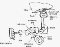
The adjustment should be rotational, of distance on the diffraction network for correct generation of the three beams, and that these adjust correctly with the lens and the detector. And over with Chinese copies of the diode ... I see it a matter of faith.
But surely there are people who have done well transplant, as always.
But surely there are people who have done well transplant, as always.
Attachments
Can you sell one pick-up?
Worked myself as service tech, kept only some test discs (Technics, Sony). Must be somewhere in the basement.
I could sell a new one, with PCB adjusted factory and sub chassis, but I do not see much sense in ebay a Chinese copy costs almost € 250:
Technics SOAD-70A laser head SL-P777 SL-P999 SL-PS840 . | eBay
Work but I see it crazy. and obviously I would not sell it for a lesser amount. Would it really make up for the repair?
What cd player do you have?
This is what I said, is to change the set and go.
But for an SL-PS900 it's unnecessary because it carries auto-tuning
It is ideal for an SL-P999, but costs as much as the player itself on ebay. So it does not make much sense, unless the sentimental issue enters the balance.
But for an SL-PS900 it's unnecessary because it carries auto-tuning
It is ideal for an SL-P999, but costs as much as the player itself on ebay. So it does not make much sense, unless the sentimental issue enters the balance.
Attachments
It's the SL-PS700. And it is not defective. Just want to have that spare part (the optical pick-up or the entire transport unit). For the next 30+ years.What cd player do you have?
Few things are necessary in the model:
Disassemble and clean the display (dust magnet), change the charging belt, condensers as an option and change of operational ones (that is recommended, but by JFets) ... it also has plenty of space for a clock with its transformer, or to separate the feeds. You are lucky.
Disassemble and clean the display (dust magnet), change the charging belt, condensers as an option and change of operational ones (that is recommended, but by JFets) ... it also has plenty of space for a clock with its transformer, or to separate the feeds. You are lucky.
By the way, I have not yet replaced the big one Black in PSU. I have Nichicon the same values, but are smaller also, hance this foam for reducing vibration wont fit.
any way - I will consider to change them.
Do you guys think it is worth add some heatsinks to those regulators in power stage?
any way - I will consider to change them.
Do you guys think it is worth add some heatsinks to those regulators in power stage?
I read through the thread and it seems that two possible improvements are not noted here (pardon me, if I am mistaken):
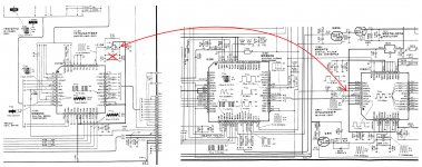
a) remove: C823/824, L801/802, CC861/862;
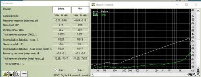
b) provide separate power lines to the analogue output stage channels (with their own reservoir capacitors near opamps). The difference can be like in a PS7xx of a friend of mine:
a) remove: C823/824, L801/802, CC861/862;
b) provide separate power lines to the analogue output stage channels (with their own reservoir capacitors near opamps). The difference can be like in a PS7xx of a friend of mine:
Attachments
Bought a second hand SL-PS900 to kill some time.
This is the second cd player I got from Technics, the first one was SL-PG490.
I am not a great fan of Technics, don't really share the filmsy, light-weight design concept Technics adopted.
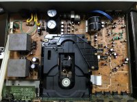
But this SL-PS900 seems different~ two transformers, linear motor for pickup, well other features did not entice me (Class AA... MASH... thousand of OPAMPs...)
I regreased the mechanism with silicon oil.
Replaced PSU caps with new and bigger size caps.
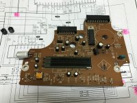
I checked the SM and noticed that there is a separate oscillator (16.9344 Mhz) on the SERVO board (MN6650) with the same frequency the DSP (MN6626) received from DAC.
Next I would remove the oscillator from the SERVO board and sync it with DSP IC.
And then put a re-clock circuit for the oscillator next to the DAC (33.8688 Mhz).
last, a COAX output for my DAC.
This is the second cd player I got from Technics, the first one was SL-PG490.
I am not a great fan of Technics, don't really share the filmsy, light-weight design concept Technics adopted.
But this SL-PS900 seems different~ two transformers, linear motor for pickup, well other features did not entice me (Class AA... MASH... thousand of OPAMPs...)
I regreased the mechanism with silicon oil.
Replaced PSU caps with new and bigger size caps.
I checked the SM and noticed that there is a separate oscillator (16.9344 Mhz) on the SERVO board (MN6650) with the same frequency the DSP (MN6626) received from DAC.
Next I would remove the oscillator from the SERVO board and sync it with DSP IC.
And then put a re-clock circuit for the oscillator next to the DAC (33.8688 Mhz).
last, a COAX output for my DAC.
Attachments

Dear Friends,
I own an SL-PS900 since the beginning of the 90's and used it (in the last 20 years) only occacionally. I never had any problems. Last evening, I listened to a CD and everything was still working fine. Today, after changing the disc, the player does not read CDs anymore (it was on overnight). It does not read any discs anymore.
If I close the tray, for a couple of seconds there is the message "D-SERVO", sometimes followed by the message "NO DISC".
The player is generally in good shape and I would like to repair it. However, I could not find any hint on the net.
Is this a known problem? Any help or advice would be greatly appreciated.
Thanks a lot in advance
Hi "HiFlyC",
it is necessary to replace all the miniature electrolytic capacitors of the "SERVO BOARD" which is located under the mechanism.
There are 12 polarized and 3 non-polarized.
This is a known maintenance on these models of CD players equipped with a "SERVO BOARD".
it is necessary to replace all the miniature electrolytic capacitors of the "SERVO BOARD" which is located under the mechanism.
There are 12 polarized and 3 non-polarized.
This is a known maintenance on these models of CD players equipped with a "SERVO BOARD".
Last edited:
Hi Technics44,
thank you very much for your answer. This info is a great help. I have the Service Manual (SM, H910511000N???) for the SL-PS900 and could follow your recommendation to a certain point:

thank you very much for your answer. This info is a great help. I have the Service Manual (SM, H910511000N???) for the SL-PS900 and could follow your recommendation to a certain point:
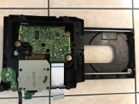
- I managed to remove the "loading unit" according to Ref. No. 9 in the SM.
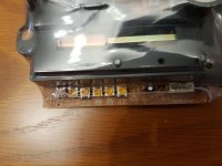
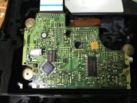
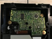
- On the PCB I could locate 12 polarized and 3 non-polarized capacitors (see image); Belonging specs can be read in the list of replacement parts. All 15 are pointing to the inside of the loading unit, i.e. the PCP has to be removed from the loading unit to replace the capacitors.
- I have not removed the servo PCB yet, because I could not find specific description in the SM and I am aware that the optical pickup is a sensitive part. I removed the 3 screws of the servo PCB, however the board can not be removed
- The servo PCB must be moved in order to replace the capacitors. How can it be done safely?
- In the Service Manual I could not find any maintenance information (e.g. to replace these capacitors). Now, while the player is open, are there any other parts that should be replaced? Is there another document, that gives more specific maintenance info compared to the SM (you mentioned " ... known maintenance on these models ...".
- Any recommendation about the quality of the capacitors or is it ok to just take from the standard sortiments you can find on Amazon/Ebay/etc.
Hello,Hi Technics44,
thank you very much for your answer. This info is a great help. I have the Service Manual (SM, H910511000N???) for the SL-PS900 and could follow your recommendation to a certain point:
The following questions come in my mind:
- I managed to remove the "loading unit" according to Ref. No. 9 in the SM.
- On the PCB I could locate 12 polarized and 3 non-polarized capacitors (see image); Belonging specs can be read in the list of replacement parts. All 15 are pointing to the inside of the loading unit, i.e. the PCP has to be removed from the loading unit to replace the capacitors.
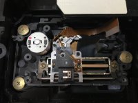
- I have not removed the servo PCB yet, because I could not find specific description in the SM and I am aware that the optical pickup is a sensitive part. I removed the 3 screws of the servo PCB, however the board can not be removed
Thank you in advance for any help.
- The servo PCB must be moved in order to replace the capacitors. How can it be done safely?
- In the Service Manual I could not find any maintenance information (e.g. to replace these capacitors). Now, while the player is open, are there any other parts that should be replaced? Is there another document, that gives more specific maintenance info compared to the SM (you mentioned " ... known maintenance on these models ...".
- Any recommendation about the quality of the capacitors or is it ok to just take from the standard sortiments you can find on Amazon/Ebay/etc.
View attachment 1064985
1) in addition to the three screws to be removed, there are the two welding points of the spindle motor to be removed to dismantle the "servo board", and finally disconnect the cable from the optical block.
The use of an antistatic bracelet is important during the phase of disconnection and reconnection of the optical unit.
Finally, it will be useful to clean the lens and also to check the condition of the CD tray belt.
2) When I wrote "known maintenance on these models", I wanted to explain that from experience, on these Technics CD player models equipped with a servo board under mechanism and passed a period of 25 to 30 years, the wear of the miniature electrolytic capacitors of this one is normal.
3) Regarding these capacitors, care must be taken to use replacement components with a height of 5mm. Higher models will prevent movement of the optical block.
@Technics44: Thank you for the your quick response. I try to take the next steps ...Hello,
1) in addition to the three screws to be removed, there are the two welding points of the spindle motor to be removed to dismantle the "servo board", and finally disconnect the cable from the optical block.
The use of an antistatic bracelet is important during the phase of disconnection and reconnection of the optical unit.
Finally, it will be useful to clean the lens and also to check the condition of the CD tray belt.
2) When I wrote "known maintenance on these models", I wanted to explain that from experience, on these Technics CD player models equipped with a servo board under mechanism and passed a period of 25 to 30 years, the wear of the miniature electrolytic capacitors of this one is normal.
3) Regarding these capacitors, care must be taken to use replacement components with a height of 5mm. Higher models will prevent movement of the optical block.
I assume the two wolding points you mentioned are the power connectors I marked in the picture? Sorry, if the answer seems obvious. I rather ask before breaking something. I am not an expert in electronis....
1) in addition to the three screws to be removed, there are the two welding points of the spindle motor to be removed to dismantle the "servo board", and finally disconnect the cable from the optical block.
...
Attachments
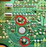
These are the solder points circled in the photo.I assume the two wolding points you mentioned are the power connectors I marked in the picture? Sorry, if the answer seems obvious. I rather ask before breaking something. I am not an expert in electronis.
- Home
- Source & Line
- Digital Source
- Technics SL-PS900