Assuming that I understand what you're asking, you're thinking that the capacitor would be there to block any DAC current output pin D.C. flow? The problem with that is the blocking capacitors then would be subject to some net D.C. charging current. Which in turn would offset ramp the current output pins to their maximum compliance voltage. Severe distortion of the signal current would result.
If there is no offset current from the DAC's current output pins, then the blocking capacitor would not be needed. However, DAC offset currents are commonly zero'd out via application of an D.C. correction current, or are first converted to voltage before being addressed post the l/V circuit.
If there is no offset current from the DAC's current output pins, then the blocking capacitor would not be needed. However, DAC offset currents are commonly zero'd out via application of an D.C. correction current, or are first converted to voltage before being addressed post the l/V circuit.
Last edited:
I do not feel comfortable, separating my ears from the high voltage by a capacitor ... I feel more comfortable putting a transformer through.
Something to meditate, I know nothing has happened, but you would leave everything to the reliability of a capacitor, I think not .... in my case.
¿More expensive transformer than a capacitor?: YES
¿Safer? ¡¡¡¡¡¡¡¡¡yeeeeeeeeeeessssssssssss¡¡¡¡¡¡¡¡¡¡ .... Without a doubt
Call me paranoid.
Something to meditate, I know nothing has happened, but you would leave everything to the reliability of a capacitor, I think not .... in my case.
¿More expensive transformer than a capacitor?: YES
¿Safer? ¡¡¡¡¡¡¡¡¡yeeeeeeeeeeessssssssssss¡¡¡¡¡¡¡¡¡¡ .... Without a doubt
Call me paranoid.
Last edited:
I do not feel comfortable, separating my ears from the high voltage by
a capacitor .. you would leave everything to the reliability of a capacitor,
I think not .... in my case.
There are film capacitors that are actually two capacitors in series.
Or, you could use two discrete capacitors in series. Transformers can
short primary to secondary, especially wide bandwidth types.
Last edited:
I am just thinking loudly: let's take a current out DAC with, say, -2 mA (sink) idle current. Now you compensate this idle current by injecting 2 mA DC into the output. The AC current output will be -2 mA to +2 mA. You have an I/V resistor 100 ohms, then you get an AC voltage 400 mVpp. The question is why you would want to AC couple between the DAC output and the I/V resistor? OK, if you want to do so, you need some 33 uF capacitor. The issue is that the reactance of this capacitor will increase with falling frequency, and it adds to the I/V resistor. At a certain point you will exceed the output voltage compliance of the DAC.
With transformer coupling you don't have this issue.
With transformer coupling you don't have this issue.
I am just thinking loudly: let's take a current out DAC with, say, -2 mA (sink) idle current. Now you compensate this idle current by injecting 2 mA DC into the output.
Injecting a correction current, while effective in nulling any current offset, then obviates the need for D.C. blocking in the first place.
Last edited:
It is possible to design a servo circuit: measure the DC voltage on the I/V resistor (use low pass filtering), and apply negative feedback on the offset compensation current.You would still need to ensure that the offset current exactly matches the mean signal current. If not you get a rising voltage on the output capacitor.
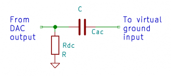
Just take the reciprocal of a normal AC coupling circuit: not a capacitor followed by a DC bias resistor and then an amplifier with a high-impedance voltage input, but a DC bias resistor followed by a capacitor and then an amplifier with a virtual ground input. Don't ask me what the advantage will be, because for a normal DAC chip, I can't think of any.
Attachments
I still don't see any reason to even think of doing this, current outputs are differential, so you don't need to null anything out, the signal is balanced already. Current output DACs work by steering discrete packets of charge to one output or the other, allowing excellent linearity as the number of packets is effectively the signal, and charge cannot be created or destroyed (leakage aside).
You can pass the currents through two resistors, a centre-tapped transformer (commonly done for RF DDS chips using current mode outputs), or a pair of I/V converters. The result is a differential voltage signal (except maybe single-ended for RF transformer). Converting to single ended is then an option, as is DC-blocking (many DACs are inherently DC capable). Seems sensible to only block DC at the point where the desired bandwidth is known, ie the amplifier input.
You can pass the currents through two resistors, a centre-tapped transformer (commonly done for RF DDS chips using current mode outputs), or a pair of I/V converters. The result is a differential voltage signal (except maybe single-ended for RF transformer). Converting to single ended is then an option, as is DC-blocking (many DACs are inherently DC capable). Seems sensible to only block DC at the point where the desired bandwidth is known, ie the amplifier input.
you just take a divider of a +/- regulated supply with good rejection ratio, that will nul the DC out, like a servo but without any feedback and no interference. It is very simple!
then you feed the Iout directly to a transistor or in the middle of 2 transistors
Just for clarity about what you propose, any DAC which needs to source or sink bias current will then require asymmetric divider resistance values in order to obtain the D.C. null, is that correct?
I still don't see any reason to even think of doing this, current outputs are differential, so you don't need to null anything out, the signal is balanced already...
Mark, the issue is that some DACs must source or sink bias current through their output pins. For example, T.I.'s PCM1794A requires D.C. paths to source an 6.2mA bias current per output pin.
Last edited:
Just for clarity about what you propose, any DAC which needs to source or sink bias current will then require asymmetric divider resistance values in order to obtain the D.C. null, is that correct?
? I did this for tda1541... I have a regulated +/- supply for the circuit. maybe 15 years ago.
So, if i place DC at the input, it screws up the transistors and gives around the same DC at output, my iv is like unity gain for DC.
So, the simple answer is to (explicitly) 1. use 50k trimpot
2. connect trimpot legs 2. to a 7.5k ohm to tda output
connect leg 1 to power supply +
connect leg 3 to power supply -
3. adjust trimpot for 0 dc at the iv output, it is almost 0V at the tda output then, because I used matched transistors
result : a good sounding dac, a nice working IV without need for an horrible sounding DC servo or DC problems.
for tda1541 it is preferable to 'sink' the current like this, my regulated supply is a constant current source and effectively acts as a current ground for the DAC.
However the tda1541 can work up to 100ohm of resistance before THD rises much.
For other dacs, the same thing applies.
you can build a regulated supply with just 10x caps, 4x transistors, 2x LED, 4x 4007 diodes, 8x resistors.
no need to have exotic regulators, like dexa etc, waste of money, they sit in the basement
Last edited:
2. connect trimpot legs 2. to a 7.5k ohm to tda output
If I read the above correctly, there is an 7.5k fixed resistor connected between the DAC output and the 50k trimpot wiper? Is that to isolate the DAC ouput from any trimpot parasitics, or perhaps to reduce the sensitivity of trimpot adjustment?
Last edited:
I am not sure, I know nothing about dacs! I understand that it is there for protection of the dac from excessive current draw, reduce parasitics, reduce the sens of the trim, it's there for many reasons... you could place 10k or nothing, it doesn't matter much I think.
I like the fact that there is always a minimum of 7.5k from the dac to the + - 16 V rails.
I like the fact that there is always a minimum of 7.5k from the dac to the + - 16 V rails.
I am not sure, I know nothing about dacs! I understand that it is there for protection of the dac from excessive current draw, reduce parasitics, reduce the sens of the trim, it's there for many reasons... you could place 10k or nothing, it doesn't matter much I think.
I like the fact that there is always a minimum of 7.5k from the dac to the + - 16 V rails.
Agreed, all of those reasons are valid.
- Status
- This old topic is closed. If you want to reopen this topic, contact a moderator using the "Report Post" button.
- Home
- Source & Line
- Digital Source
- IOUT DAC capacitive coupling?