I want to be hones: I am not looking forward to deciphering several dozen pictures without any comments to what is what.
That may be one reason why reactions are lukewarm.
Jan
The FET's on these schematics do nothing they are connected with 0 volts on all three terminal i.e. at the zero point of their triode region (a simple resistance from drain to source, like a switch). Shorting them out gives the same result.
FALSE!The FET's on these schematics do nothing they are connected with 0 volts on all three terminal i.e. at the zero point of their triode region (a simple resistance from drain to source, like a switch). Shorting them out gives the same result.
I'm listening to the thing right now and it is better than you might think!
It will take you a few hours or less to build it , you can do it just with one section .You don't need two in parallel.
Try it yourself and then come back!
Last edited:
")
FALSE!
I'm listening to the thing right now and it is better than you might think!
Good for you, sorry I've wasted enough time on this and frankly it could be a put on as far as I am concerned.
Well...people get tired or nervous from time to time, so i wouldn't hurry up betting until i'd build the damn thing.In the end it is just a fet transistor and an op-amp...Piece of cake for both of you!Well Scott being right and you enjoying listening to it can both be true. Knowing Scott I'm not going to bet against him
Just imagine what it will sound like when you get it right and you start - gasp! - listening to the music!
Jan
Until then you're both at loss.
Last edited:
so i wouldn't hurry up betting until i'd build the damn thing.
Much easier for you to short out the FET and see that nothing happens.
I will simply stop here .
The best thing I've heard all day
Well...people get tired or nervous from time to time, so i wouldn't hurry up betting until i'd build the damn thing.In the end it is just a fet transistor and an op-amp...Piece of cake for both of you!
Until then you're both at loss.
Well, why would I build it? What's the point? I'm sure there's sound coming out of it. Nobody said there isn't. And its 'quality' just to use a lump expression, is all very personal and such testimonials are not very helpful for other personals.
The point was a technical one, an issue of circuit design. What's the point, in that context, of building it? Why are you ducking that?
Jan
The fact that i had this idea is just an accident of evolution...
Right, earmarks of troll/put on. This is so stupid it can't be serious.
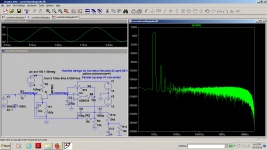
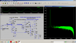
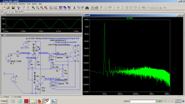
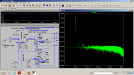
This circuit's issues are outlined by the LtSice simulations...The main debate was about the fet biasing.I personally had the same questions before Scott Wurcer put them here , and not only about the fet bias, but also about the relationship of the BJT transistor bias to the THD figures which i finally understood after a few hundred simulations ,W
The point was a technical one, an issue of circuit design. What's the point, in that context, of building it? Why are you ducking that?
Jan
but i remember that you asked me rhetorically:
Why would I look at so many simulations? Well ...the answer lies in those simulations.I want to be hones: I am not looking forward to deciphering several dozen pictures without any comments to what is what.
That may be one reason why reactions are lukewarm.
Jan
Now there's a movie I made for you.
Have fun!
YouTube
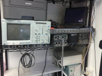
And by the way the photos attached are made by me with my books 3 years ago in a lab where i had the chance to work in for a project that went to CES and was branded as high end...I kinda know what this sport looks like .My Boos(actually GOD!!!) at the time insisted for me to start learning LtSpice and i'm thankful for life!
Now I thank you both for your kind comments!
Attachments
Last edited:
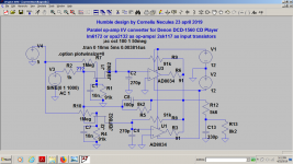
OPA2132 sounds definetely better with this design and player as the current noise is the most important here with the 8k2 feedback resistor and lower iout current.
I started with a bipolar transistor buffer based circuit on a Philips cd 610 based on tda1543 which outputs about 2ma of current .I used there some very old op-amps LM833 and 2sa1038 described here:
https://www.diyaudio.com/forums/dig...cd-players-enhancing-noise-6.html#post5688490
In the mean time i realized many of the wrong ideas i had initially.
I fancied of putting a similar stage on a Sony player based on TDA1543 (4ma Iout), but i finished by using the LM6172 after reading Abraxalito's recommendation and i couldn't be more pleased with the result.
With the Denon i had no chance of finding the right op-amp for cheap working in the original setup as the output is very low , just 1ma max so i tried first some simulations with bjt transistors, but what i didn't like about that was that no matter the bias, the transistor base would steal some tens of microamps of dc current from the DAC output and the current was already low plus i didn't know how the dac would react to that.
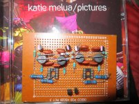
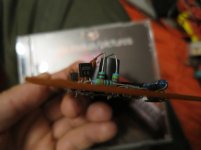
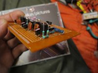
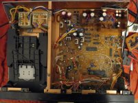
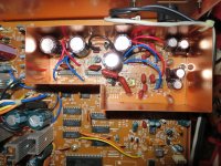
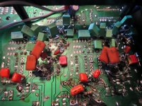
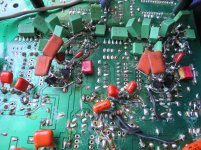
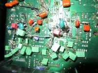
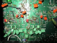
I actually built a bjt version which you can see in the photos based on 2sa1038, an exceptionally low noise transistor that i have a few.I will probably try it on tda1541 based dac chips.
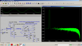
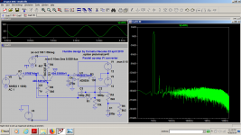
That is how i got to the fet circuits as the gate wouldn't need any current at all.The THD in fet circuits weren't as great as with the bjt simulations, but here's where i stopped believing the simulator as i didn't factored in the power supply noise and the fet being referenced only to ground and being filtered with a much smaller in value and in size capacitor I'd get the lowest noise POSSIBLE.
Of course you'd have slightly better thd numbers with a fixed bias for the FET transistor, but i thought of trying it first as the simulator usually doesn't lie to me.It does sometimes, but not all the time.
I could try an explanation for why the Virtual ground is called Virtual...but i won't risk it. I'm not a a theory Guru...I just follow my intuitions and at least for 17 years in this area they had proved right most of the time.
I started with a bipolar transistor buffer based circuit on a Philips cd 610 based on tda1543 which outputs about 2ma of current .I used there some very old op-amps LM833 and 2sa1038 described here:
https://www.diyaudio.com/forums/dig...cd-players-enhancing-noise-6.html#post5688490
In the mean time i realized many of the wrong ideas i had initially.
I fancied of putting a similar stage on a Sony player based on TDA1543 (4ma Iout), but i finished by using the LM6172 after reading Abraxalito's recommendation and i couldn't be more pleased with the result.
With the Denon i had no chance of finding the right op-amp for cheap working in the original setup as the output is very low , just 1ma max so i tried first some simulations with bjt transistors, but what i didn't like about that was that no matter the bias, the transistor base would steal some tens of microamps of dc current from the DAC output and the current was already low plus i didn't know how the dac would react to that.
I actually built a bjt version which you can see in the photos based on 2sa1038, an exceptionally low noise transistor that i have a few.I will probably try it on tda1541 based dac chips.
That is how i got to the fet circuits as the gate wouldn't need any current at all.The THD in fet circuits weren't as great as with the bjt simulations, but here's where i stopped believing the simulator as i didn't factored in the power supply noise and the fet being referenced only to ground and being filtered with a much smaller in value and in size capacitor I'd get the lowest noise POSSIBLE.
Of course you'd have slightly better thd numbers with a fixed bias for the FET transistor, but i thought of trying it first as the simulator usually doesn't lie to me.It does sometimes, but not all the time.
I could try an explanation for why the Virtual ground is called Virtual...but i won't risk it. I'm not a a theory Guru...I just follow my intuitions and at least for 17 years in this area they had proved right most of the time.
Attachments
Last edited:
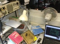
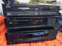
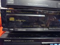
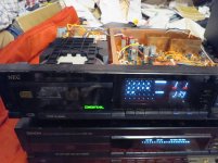
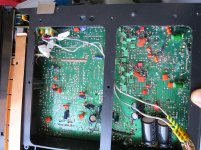
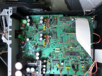
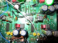
Part of the interest in making a very low noise i/v converter for low input currents comes also from the fact that ...just by accident i picked two very rare and old cd players that few people even ever saw with 1ma output dacs that you can see in the picture.I won't open the jvc tonight too.Its using m5220 as i/v stage though...
.Actually the NEC player is a real mistery for me because of some special low pass filters which were described in a review but i couldn't find the schematic for that.Next week i should be into it if iget the time.For the moment i really enjoy my DENON .The NEC player doesn't output any sound although it plays now so i'd also need to fix it.
.Actually the NEC player is a real mistery for me because of some special low pass filters which were described in a review but i couldn't find the schematic for that.Next week i should be into it if iget the time.For the moment i really enjoy my DENON .The NEC player doesn't output any sound although it plays now so i'd also need to fix it.
Attachments
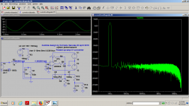
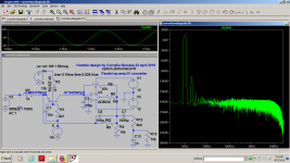
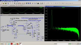
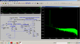
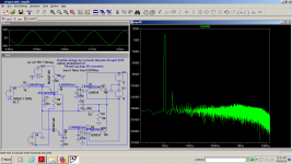
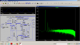
As I've been challenged By Scott...I thought of adding the 1 meg resistor back to make a full divider for biasing the j-fets.
To be truthful...I can't hear a clear difference right now.It's just the noise floor that looks to be a bit higher, but it might be just an illusion as i was expecting it or just because i'm a bit tired .I'm going out now as i think my ears are tired of such long listening tests.
I don't have a model for 2sk117 so i'm just doing blind tests.
As I obtained the 5v from two series regulator 78m12(JRC),78m09(JRC), 78L05(JRC) loaded also with the analog VCC of the PCM1701 DAC and an additional resistor for 5ma idle current , the supply for this trz bias should be noise free then the 10nf should do the rest when signal is present...I may need to compare it for longer time.I will leave it like this for a day or two than disconnect the resistors.
That resistor might need to have a different value too.
Attachments
I finally understood what Scott asked...We were on different lines yesterday...
Indeed , the fet input act as a controlled resistor, it can be shorted out with a 22 ohm resistor as Scott pointed out, but it acts like a better buffer when paralleling more op-amp sections in order to solve the offset problems and i can also load the input signal with more capacitance to filter any transient before the signal gets into the op-amp input or using less distributed capacitance for a better phase response, it works both ways.
It has higher output drive with more op-amps in parallel, we could use even quads with 4 transistors in parallel per channel for lower noise , and with higher output dac's than mine we can use lower feedback resistor values and higher capacitance without being worried that the op-amp won't be able to drive it.Wuth a carefully filter between trz buffer and op amp so that we can't loose the phase response, we might simply remove completely the need for any additional low pass filter although more op amps in parallel can drive very low impedance passive filters that can work miracles on the sound.
More fet input op-amps in parallel means also lower voltage noise so nothing is really lost in terms of noise figures.
I've listened to the player the whole day today too and it performs very well.I can't hear any noise and i actually invited a well known guitar player in my country which is a friend of mine for about 15 years (he has some very expensive RME equipment for recording, as he also got a television and sound engineering diploma, making his own material for a decade now and he listened to my player for more than an hour telling that the sound is quite good actually .He's a musician , not an audiophile guy...so he won't tell anything about silky highs though...He's just a professional and his simple OK is much better than 100 audio-phools words.
I myself have some Audient equipment for professional recording with a very good asynchronous usb , xmos, pcm 1792...but i can't complain about the quality of this ugly and old cd player...
Last edited:
Indeed...I can only contemplate my stupidity which is indeed original and awesome!
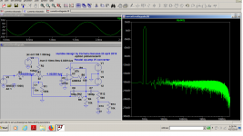
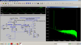
The fet in the circuit has no benefit over a damn resistor...nor the "nested feedback".That second feedback isn't necessary not even in the bipolar tranzistor circuits as you can see in the last pictures.
The real static resistance value of 2sk117 is around 70 ohms.Just much harder for the simulator (5 minutes waiting for the results)when i put a simple resistor which is a bit weird...
I'll go back to the bipolar buffer soon for higher current output dacs.
70 ohms is not a lot of damping and it's a bit too expensive to use j-fet transistors instead of 68ohms resistors.I just don't know how a a 68 ohms fet transistor noise is compared with a real 68ohm resistor.Probably higher.
I just came to base one...2x 2sk170 resistance is about the same with Abraxalito's 31 ohm resistor...
The output is 0.3v on both op-amps ouputs, but now i'm really curious if 2 identical 68 ohms resistors will give the same offset so i did NOTHING with these fets as Scott said...
Now i really have to try 4 resistors and 4 amps in parallel so that i can make a sufficiently higher damping of the dac output on higher values capacitors and better
SAD ...
Should I go back to the same expensive smd op-amps that burn like hell , need special pcb requirements and never meet the thd specs unless i give them the smallest power supply that can do the job?
O course not!
I still have a lot of clean power at my disposal to drive the most savage passive filter while the buffers, no matter how they are made are rounding the dac output transients before they reach the op-amp output never causing slew rate limitations...Well...That is a text that tonight i need to believe in!.
Attachments
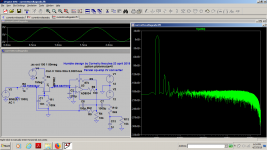
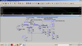
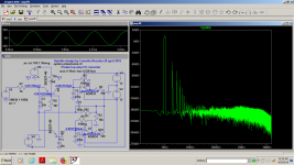
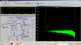
After failing miserably with the fet version in the sense that i could have used 68 ohms instead of 2sk117(the offset with resistors is around 500mv and the offset with 2sk117 front end was 350mv...not much of a difference),
I just came back to the BJT versions and i made them as good as possible for the job.
I have about 20...50mv dc output and i managed to have very low absorbed dc currents from the dac output(300na for two pnp transistors and 900na for two npn trz.) with regular value resistors.In reality i'm going to use precision fet op-amps and the offset will be lower.I have one more theoretical problem to solve but i won't tell it right now.
Now...THE BIG IF, is if it really works with only a global feedback in the front end bipolar transistors.Removing that local feedback got me a lot of apparent performance.
That is something that i'm going to find out tomorrow.
Attachments

Last edited:
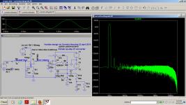
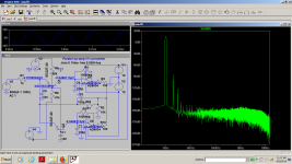
Just some more investigations around the dc bias and offset related to distortion figures.
In the end, for 16 bit dac , 1ma output , i can simply use those paralleled 68 ohms resistors per channel for pretty much the same results as they offer similar noise performance and enough damping for the dac output capacitors , accepting the 500mv ouput offset(lager than the transistor buffering ) with acceptable distortions when coupling through Nichicon Muse bipolars and being prepared to deal with phase lag compensation.
In the end, for 16 bit dac , 1ma output , i can simply use those paralleled 68 ohms resistors per channel for pretty much the same results as they offer similar noise performance and enough damping for the dac output capacitors , accepting the 500mv ouput offset(lager than the transistor buffering ) with acceptable distortions when coupling through Nichicon Muse bipolars and being prepared to deal with phase lag compensation.
Attachments

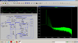
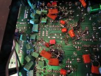
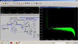
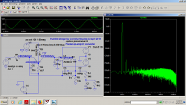
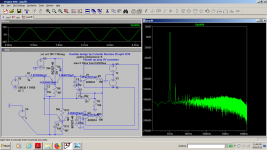
After lots of trials on my Denon i just came at the same conclusion i had before...There's no benefit in coupling bipolar transistors at the outout of a dac with only 1ma of output.I just finished with two op-amps in parallel with 65 ohms input resistor and 330pf cap on each op amp.
Scott was completely rignt ...That fet was just a damn resistor so resistors are cheaper.The sound couldn't be any better .
What's interesting now and what the simulation simply couldn't tell me is that i have less than 20mv offset at the output when i put the same resistors on both channels...I have no idea why i have different offset if i put different resistor values on each channels( i mean that i can have 2x 65 ohms on one channel with two paralleled op-amps and 2x 1kohm on the other channel and i get different offsets .When i pit the same value for all 4 resistors i get no offset, ot at least very low dc offset...
Another thing that the simulator can't see and i have no explanation for is why , at the putput of each paralleled op amp, before the output resistor(pin 7-1) i have exactly +-4 volts on each channel and allmost no voltage at the output after the 91 ohms...
The most interesting trial would be to add two more op-amps in parallel filtering the input even more.
The only interesting thing to do more on this player would be to add a higher slew rate op-amp as in the "best of both worlds" app document to raise the input op-amps slew rate even more .That could be done with lm6172 as i have two more for trials.
I will try the bipolar front end only on higher output dacs .
Attachments
- Status
- This old topic is closed. If you want to reopen this topic, contact a moderator using the "Report Post" button.
- Home
- Source & Line
- Digital Source
- New i/v stage in town