As i found some more time to perfect my i/v stage started here
https://www.diyaudio.com/forums/dig...cd-players-enhancing-noise-6.html#post5688490
I thought that it now deserves an entirely new topic because it started to look really promising.
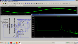
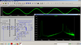
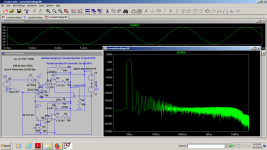
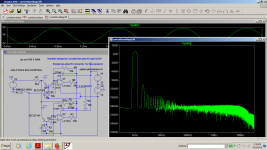
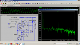
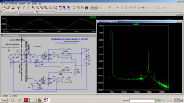
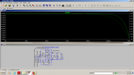
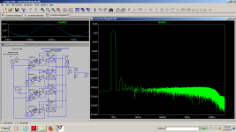
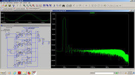
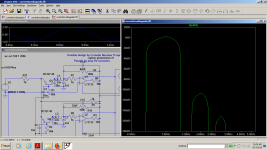
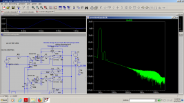
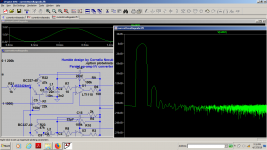
I started this exploration on a tda1543 and when i wanted to find the best op-amp for an 8x upsampling dac based on pcm1701 which should have about 0.5...1ma max IOUT , i simply found out that there aren't many choices out there for a good op amp to do the job because you need very low voltage and current noise along with good output drive and fairly good slew rate to deal with the ultrasonic trash.
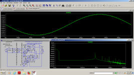
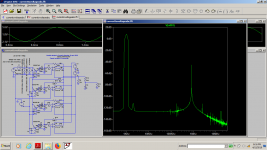
I used the same idea used in Denon dcd1560(my best cd-player) of shunting the iout with a capacitor but i wanted to do it the right way, so that both the dac and the op-amp would harmoniously fight each other.
I had to deal with some lack of knowledge about how to sim a real dac output and make the simulator tell some beautiful lies, but now i know the WAY!
https://www.diyaudio.com/forums/dig...cd-players-enhancing-noise-6.html#post5688490
I thought that it now deserves an entirely new topic because it started to look really promising.
I started this exploration on a tda1543 and when i wanted to find the best op-amp for an 8x upsampling dac based on pcm1701 which should have about 0.5...1ma max IOUT , i simply found out that there aren't many choices out there for a good op amp to do the job because you need very low voltage and current noise along with good output drive and fairly good slew rate to deal with the ultrasonic trash.
I used the same idea used in Denon dcd1560(my best cd-player) of shunting the iout with a capacitor but i wanted to do it the right way, so that both the dac and the op-amp would harmoniously fight each other.
I had to deal with some lack of knowledge about how to sim a real dac output and make the simulator tell some beautiful lies, but now i know the WAY!
Attachments
-
 ivpcm17011.png78.8 KB · Views: 713
 -
 ivpcm170110.png85.4 KB · Views: 143
 -
 ivpcm17019.png88.4 KB · Views: 108
 -
 ivpcm17018.png84.6 KB · Views: 112
 -
 ivpcm17017.png87.9 KB · Views: 106
 -
 pcm17016.png74.2 KB · Views: 94
 -
 ivpcm17015.png77.3 KB · Views: 660
 -
 pcm17014.png72.6 KB · Views: 670
 -
 ivpcm17013.png79.4 KB · Views: 674
 -
 ivpcm17012.png66.4 KB · Views: 706
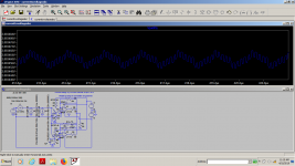
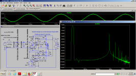
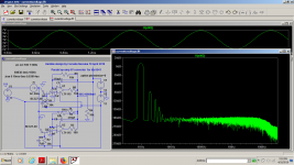
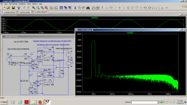
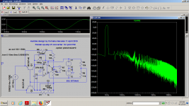
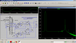
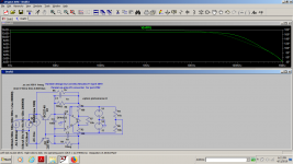
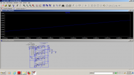
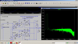
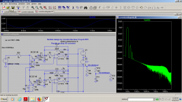
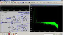
I just realized that i have the wrong bias too, as i got the old sim for tda1543 which was biased at 2v ...that's not a problem though, i can reference it to the negative V.
I'll try doing this the right way...but at least the last numbers with the same "no zout" were 85 db for H2 max.
Now...how the hell do i sim the dac z out? Just by making the voltage source series resistance 1k doesn't look realistic.I get the same results...
I'll try doing this the right way...but at least the last numbers with the same "no zout" were 85 db for H2 max.
Now...how the hell do i sim the dac z out? Just by making the voltage source series resistance 1k doesn't look realistic.I get the same results...
Attachments
Last edited:
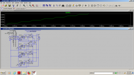
Could somebody help me with how to sim the dac output impedance the right way?I simply don't know...Is it just by making the series resistor of the voltage source or by adding a series resistor to the current output?
Attachments
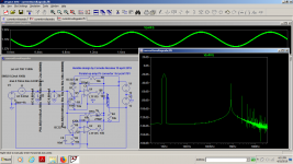

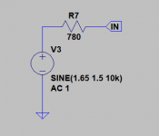
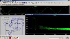
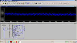
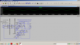
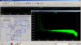
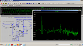
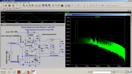
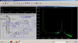
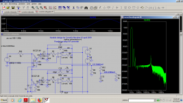
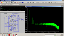
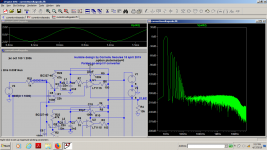
Before i play with your version of dac out i just wanted to make some more sims playing with the trz bias.I have a few versions with -140db(0.5ma in-pcm1701), 120db(4ma in-tda1541), then some versions aiming at only 100db .I also increased the input capacitor to 1nF.it might work better for the real thing and then i would probably need less than 100pf for the feedback.Add a 1k resistor in serie to a voltage source and delete the current sources. I do like this to simulate a es9018
Attachments
Last edited:
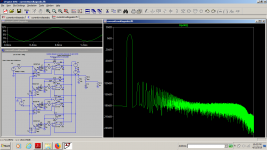
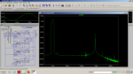
I used the resistor + voltage source.At 1khz the results aren't far from my voltage-current source version, at -110...-130db as they are identical at 10khz, at about -40..50db for the second and third hamonic, but i wonder who's going to hear it...
Attachments
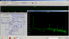
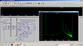
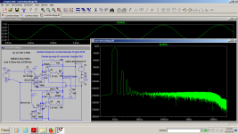
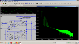
As i have 2 pcs of opa4227 i thought of a quad parallel version and you have here the single ended versions for 1ma...7ma, for older type of iout dac's .There's not a single sim with more than-120db thd for the first harmonics using lt1115 .More opa1632 in parallel for the balanced version shouldn't be any tougher...
I also have some opa2228 so i'll try them too with a little bit of compensation.
Also some old good njm chips with lower noise than njm2068, unity gain stable , stable also within 0.25v to the rail supply output, able to drive 400 ohms at V rail -0.25v and 3 times higher slew rate than opa2227...but that is a secret for now")
I know there's one graph showing -160db...It's just an illusion
I also have some opa2228 so i'll try them too with a little bit of compensation.
Also some old good njm chips with lower noise than njm2068, unity gain stable , stable also within 0.25v to the rail supply output, able to drive 400 ohms at V rail -0.25v and 3 times higher slew rate than opa2227...but that is a secret for now
I know there's one graph showing -160db...It's just an illusion
Attachments
Last edited:
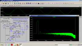
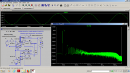
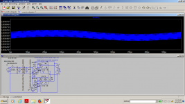
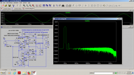
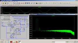
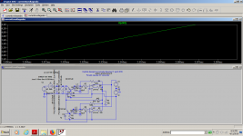
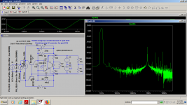
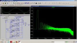
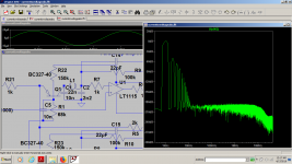
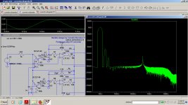
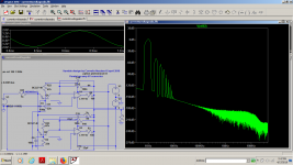
There's a real flaw in the modeling the dac output, which is that the sim is not senzitive to the current taken for the dc bias of the transistor in figuring out that the SNR will drop a lot because of that.So i made the base resistor higher,even aded a divider from v+ to provide the transistor some external current and the distortion figures modified to really worse by 50 db, but i don't need more than 100 db SNR for an old dac anyway.This things needs to be measured in a real setup.I don't trust at all these figures.I know it works pretty well as i already built one version, but it shouldn't provide such great numbers as it did before with low rez for trz bias.
Attachments
Last edited:
Could somebody explain me this riddle? Why is that when i add external bias the thd is worse? Shouldn't be otherwise?
Attachments
Besides that, testing with a sinewave input simply isn't at all realistic when the source in reality is a DAC with very fast edges between sample points. When the opamp model is a macromodel (as most are) then THD is moot to begin with.
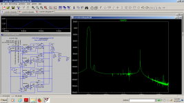
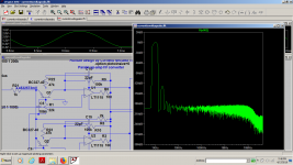
Having just scrolled up a bit, if you're putting in a filter inspired by me do your best to have decent damping - that ~1MHz high Q resonance looks potentially problematic. Oh and also I put my filters prior to any active circuitry (including discrete transistors).
Having just scrolled up a bit, if you're putting in a filter inspired by me do your best to have decent damping - that ~1MHz high Q resonance looks potentially problematic. Oh and also I put my filters prior to any active circuitry (including discrete transistors).
Last edited:
Besides that, testing with a sinewave input simply isn't at all realistic when the source in reality is a DAC with very fast edges between sample points.
This is true, but I think the sine input is not a big problem. The measured results of I/V converters that I've seen seem to be as-expected to me and track with the sine input distortion. You can see excellent measured results with NE5534 and AD797, neither of which are fast by modern standards.
- Status
- This old topic is closed. If you want to reopen this topic, contact a moderator using the "Report Post" button.
- Home
- Source & Line
- Digital Source
- New i/v stage in town