This is the second device I deliberately bought to be modified.
As expected, also this DAC did not sound like it should, given its modern design and its 500 bucks pricepoint.
Luckily by now price has dropped considerably.
To be fair, the presentation is not so bad, though far from being what could be expected from an AK4490, dual mono TPA6120A2, dual clock DAC, mostly lacking stringent bass down low, overall transparency, intimacy and "3D" rendering.
The good news is, that there seems to be no hard edginess as usually found in many lower market DACs.
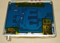
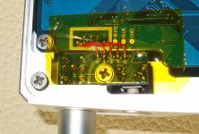
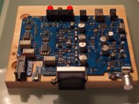
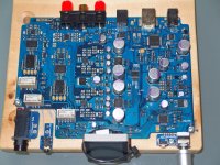
Once opened one can find a nicely layouted board, with a plethora of voltage regulators and some funny rework too
")
As expected, also this DAC did not sound like it should, given its modern design and its 500 bucks pricepoint.
Luckily by now price has dropped considerably.
To be fair, the presentation is not so bad, though far from being what could be expected from an AK4490, dual mono TPA6120A2, dual clock DAC, mostly lacking stringent bass down low, overall transparency, intimacy and "3D" rendering.
The good news is, that there seems to be no hard edginess as usually found in many lower market DACs.
Once opened one can find a nicely layouted board, with a plethora of voltage regulators and some funny rework too
Attachments
-
 bottom_1.JPG206.5 KB · Views: 384
 -
 rework_3.JPG200.4 KB · Views: 212
 -
 rework_2.JPG300.7 KB · Views: 210
 -
 rework_1.JPG363.7 KB · Views: 207
 -
 rear_1.JPG191 KB · Views: 367
 -
 bottom_4.JPG146.2 KB · Views: 369
 -
 bottom_3.JPG262.8 KB · Views: 365
 -
 bottom_2.JPG219.2 KB · Views: 373
 -
 top_view_1.JPG234.7 KB · Views: 215
Last edited:
First modification finally done.
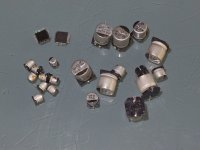
As almost always, I started out by upgrading the inferior electrolytic capacitors used by SMLS.
As there are not that many recommendations about SMD lytic caps for audio applications, nor there was that much a variety of typs available for me that fit size and voltage requirements, I settled to OS-CON polymer electrolytic capacitors.
To make it short, happily the result is a great improvement in auditory spaciousness , overall clarity and details all over the audio bandwidth without obvious side effects. Presentation is fulminate and with authority.
So far so good, but this first step implied hurdles and fails, maybe worth to tell as a word of caution for those that possibly try to go the same route.
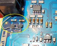
I considered myself as very experienced in soldering, even on small parts at cramped spaces, but certainly I was not prepared for the challenges to hand solder 48-pin LQFP or SMD resistors the size of a needle tip.
For unsoldering the SMD lytics I used my ERSA tweezers (https://browse.startpage.com/do/sho...sp=47ca218586980973d21add398070b807&t=default) with appropriate tips, but unfortunately I did not mask nearby parts so I made shorts at both AKM4493 DAC chips.
All my efforts to get them cleared failed and so I decided to unsolder them and buy replacement parts (https://www.digikey.com/product-detail/en/akm-semiconductor-inc/AK4493EQ/974-1162-ND/8124021).
I prepared desoldering first by again unsoldering all close by lytics and also carefully masking all nearby SMD parts with Kapton tape.
By setting my hot air gun to 420°C and the lowest air volume, desoldering took about 30sec.
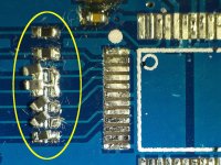
No pads got damaged, but masking obviously wasn't good enough, so several SMD resistors partly got unsoldered too.
I used my good loupe (Waldmann - Engineers of Light - SNLQ) that served me for years now, for soldering and inspection afterwards, but frankly, loupes are definitely not an appropriate choice for such extreme delicate work, nor was my finest tip on the Micro Tool, so an ERSADUR 0212RD with 0.2mm radius needle tip (Ersa-Shop - ERSADUR-Lotspitze, bleistiftspitz 0.2 mm o) and an Andonstar ADSM302 USB microscope (YouTube) was in order.
The Andonstar ADSM302 USB microscope really is great, very sharp and clear, even more so when connected to a large screen via HDMI - though I sadly did not manage to marry it with an android OLED tablet by a GTO adapter.
The ERSADUR 0212RD tip proved to be the absolute right choice for resoldering the SMD resistors but for anything else, there simply is not enough heat transfer to that needle tip and it certainly does not allow to put much force either.
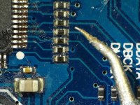
So for soldering the two new AKM4493 DAC chips, I had to go back to a "bigger" tip on my ERSA Micro Tool (0DIG20A27 - Ersa DIGITAL2000 Lotstation 80W, 230V mit Micro Tool Lotkolben 20W, 24V, antista). As I already had bad experiences with shorts on the 48-pin LQFP chip, I decided to solder it pin by pin, after carefully removing all old solder from the pads.
Working under a USB microscope needs some getting used to and a pitch of 0.65mm needs a very steady hand too.
To remove further shorts that unavoidably happened again, I had best results in avoiding desoldering braid and using instead a fine silver litz wire I had at hand, that sucked the excessive solder most easily when also using some "no whash" flux. I always oriented the litz wire as well as the soldering tip straight in the direction of the pins, which is what worked out the best.
As almost always, I started out by upgrading the inferior electrolytic capacitors used by SMLS.
As there are not that many recommendations about SMD lytic caps for audio applications, nor there was that much a variety of typs available for me that fit size and voltage requirements, I settled to OS-CON polymer electrolytic capacitors.
To make it short, happily the result is a great improvement in auditory spaciousness , overall clarity and details all over the audio bandwidth without obvious side effects. Presentation is fulminate and with authority.
So far so good, but this first step implied hurdles and fails, maybe worth to tell as a word of caution for those that possibly try to go the same route.
I considered myself as very experienced in soldering, even on small parts at cramped spaces, but certainly I was not prepared for the challenges to hand solder 48-pin LQFP or SMD resistors the size of a needle tip.
For unsoldering the SMD lytics I used my ERSA tweezers (https://browse.startpage.com/do/sho...sp=47ca218586980973d21add398070b807&t=default) with appropriate tips, but unfortunately I did not mask nearby parts so I made shorts at both AKM4493 DAC chips.
All my efforts to get them cleared failed and so I decided to unsolder them and buy replacement parts (https://www.digikey.com/product-detail/en/akm-semiconductor-inc/AK4493EQ/974-1162-ND/8124021).
I prepared desoldering first by again unsoldering all close by lytics and also carefully masking all nearby SMD parts with Kapton tape.
By setting my hot air gun to 420°C and the lowest air volume, desoldering took about 30sec.
No pads got damaged, but masking obviously wasn't good enough, so several SMD resistors partly got unsoldered too.
I used my good loupe (Waldmann - Engineers of Light - SNLQ) that served me for years now, for soldering and inspection afterwards, but frankly, loupes are definitely not an appropriate choice for such extreme delicate work, nor was my finest tip on the Micro Tool, so an ERSADUR 0212RD with 0.2mm radius needle tip (Ersa-Shop - ERSADUR-Lotspitze, bleistiftspitz 0.2 mm o) and an Andonstar ADSM302 USB microscope (YouTube) was in order.
The Andonstar ADSM302 USB microscope really is great, very sharp and clear, even more so when connected to a large screen via HDMI - though I sadly did not manage to marry it with an android OLED tablet by a GTO adapter.
The ERSADUR 0212RD tip proved to be the absolute right choice for resoldering the SMD resistors but for anything else, there simply is not enough heat transfer to that needle tip and it certainly does not allow to put much force either.
So for soldering the two new AKM4493 DAC chips, I had to go back to a "bigger" tip on my ERSA Micro Tool (0DIG20A27 - Ersa DIGITAL2000 Lotstation 80W, 230V mit Micro Tool Lotkolben 20W, 24V, antista). As I already had bad experiences with shorts on the 48-pin LQFP chip, I decided to solder it pin by pin, after carefully removing all old solder from the pads.
Working under a USB microscope needs some getting used to and a pitch of 0.65mm needs a very steady hand too.
To remove further shorts that unavoidably happened again, I had best results in avoiding desoldering braid and using instead a fine silver litz wire I had at hand, that sucked the excessive solder most easily when also using some "no whash" flux. I always oriented the litz wire as well as the soldering tip straight in the direction of the pins, which is what worked out the best.
Attachments
Last edited:
Now that the M9 already is at a not too shabby level, I need some time to see what exactly enjoys me of that design and what things I'd like to change and also, to figure out how to possibly get there
All in all I'm after a presentation that for me stands the test of time, IMO the hardest challenge of all.
Some ideas are about voltage rail bypassing with ultra caps (I already had good results with, but demand for a lot of elaborate safety measures in an automated setup), bridging the digital pot, or about close by bypassing the tantals in the analogue part.
Lets see...
Last edited:
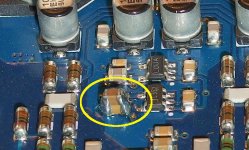
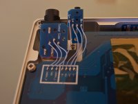
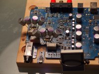
My next step was to bypass the tantals of the TPA1620 headphone chip
As there is very little space available and the pads of this board are extreme fragile, I decided to take a different approach this time and bypassed the tantals with Os-Con polymer caps.
The picture shows the stage of proof of concept rather than what I would like to arrange them in the end.
Nevertheless, it turned out to be a definite improvement, especially in the high frequency range and in terms of intimacy.
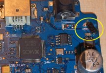
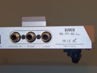
Until now, I only used the 6.3mm 3-pin plug for convenience, but thinking a little bit longer about reference mass connections, the picture makes absolute clear that the 6.3mm three pin OUT never ever will work on top level in this device.
The M9 features a quasi dual mono design, thus the mass reference points of the right and the left channel are separated by some distance and never ever will be 100% in sync.
Thus, before anything else, I have to solder a dual mono adapter for the mini-XLR plugs on my 4-wire AKG, that hopefully will solve some subtle beat at lower frequencies, I pique myself now and then.
As there is very little space available and the pads of this board are extreme fragile, I decided to take a different approach this time and bypassed the tantals with Os-Con polymer caps.
The picture shows the stage of proof of concept rather than what I would like to arrange them in the end.
Nevertheless, it turned out to be a definite improvement, especially in the high frequency range and in terms of intimacy.
Until now, I only used the 6.3mm 3-pin plug for convenience, but thinking a little bit longer about reference mass connections, the picture makes absolute clear that the 6.3mm three pin OUT never ever will work on top level in this device.
The M9 features a quasi dual mono design, thus the mass reference points of the right and the left channel are separated by some distance and never ever will be 100% in sync.
Thus, before anything else, I have to solder a dual mono adapter for the mini-XLR plugs on my 4-wire AKG, that hopefully will solve some subtle beat at lower frequencies, I pique myself now and then.
Attachments
Last edited:
- Status
- This old topic is closed. If you want to reopen this topic, contact a moderator using the "Report Post" button.
- Home
- Source & Line
- Digital Source
- don't trash your SMSL M9 DAC, pimp it!