Hi everyone.
Long time reader here after a couple of years of lurking I decided to start my own project with as big example https://www.diyaudio.com/forums/digital-source/272147-tda1549-marantz-cd48.html .
I found a Marantz CD 48 for free as it didnt work anymore. I just put in a disc and received the error "No disc". I can hear hear the laser trying to focus but the disc doesnt spin. I tried cleaning the lens to no avail.
Are there any options to fix this without replacing the module? If i would replace it should i search for a cheap working cd player with the same CDM12.1 or buy a new compatible VAM1201?
Before repacing the module, try cleaning the internals of the spindle motor. Assuming it is a dc motor, disconnect it from the circuit board and power it for a few seconds in either direction from a 9V DC source. This should clear out any contamination. If this doesn't work, try a squirt of switch cleaner through the ventilation holes near the connector. This approach worked for my Technics CD player which was failing to read the table of contents (TOC) of the disc.
Sadly no luck , seemed the laser was done. Ordered a new VAM1201 on ebay. Also have an eye on a working Philips CD 911 to use as a doner if needed.
A bit of background I dont have any electronic engineering experience, I have retro gaming as a hobby and did my own modifications so I got myself some decent equipment like soldering station/multimeter etc.
Delicate audio equipment is a whole different story so I persue this as a learning experience not just to upgrade the hardware but also understand why certain choices are made.
While waiting for the CDM I was looking at the service manual ( found here PHILIPS CD751 SM Service Manual download, schematics, eeprom, repair info for electronics experts ) and figured ill start with recapping the whole thing before adding more parts.
As far as powersupply caps the logic seems to be low ESR / high ripple for example the Panasonic FC series and one cant go wrong using bigger capacitance.
2536 : 4700µF/16V -> 8200µF/16V https://be.farnell.com/panasonic/eeufc1c822/cap-8200-f-16v-20/dp/9692126
2538 : 3300µF/16V -> 4700µF/16V https://be.farnell.com/panasonic/eeufc1c472/cap-4700-f-16v-20/dp/9692100
2542 : 1000µF/10V -> 2200µF/10V https://be.farnell.com/panasonic/eeufc1a222/cap-2200-f-10v-20/dp/9691979
2540 : 220µF/50V -> 1000µF/50V https://be.farnell.com/panasonic/eeufc1h102/cap-1000-f-50v-20/dp/9692460
2560 : 330µF/16V -> 1000µF/16V https://be.farnell.com/panasonic/eeufc1c102s/cap-1000-f-16v-20/dp/1848432
From there on i am not sure what to pick cap wise, so I'll appreciate some input. Most common one after the psu is the 22µF/40V axial cap ( picture @ http://www.lampizator.eu/lampizator/REFERENCES/Philips CD751/IMG_5161.jpg ). Random caps i looked up with same values are quite expensive , i wondered if i should use radial equivalent instead and solder them on the bottom side cause of room constraints. But im not sure what purpose they have and what replacements to pick , any available at https://be.farnell.com i can order.
Thanks in advance.
Last edited:
Still waiting for the laser unit to arrive, so I was looking at the other caps to replace.
After the OPAMP are 2306/2307 which are currently 100µF Silmic I bipolar caps. Since Silmic II are not bipolar anymore i plan to replace them with Nichicon Muse ES series which are audio/bipolar caps. Probaly going for 100µF/50V since these would fit with same lead width.
All the following caps are currently 47µF/25V.
2302/2303 are between DAC and OPAMP, planned to replace these with Nichicon KZ premium audio caps. i dont know when talking about audio signals if bigger is better capacitance wise but up to 330µF/25V would fit perfectly.
The following im not sure what best to use:
-2331 -> DAC VDDD
-2333 -> DAC VDDA
-2335 -> DAC VDDO
-2310 -> DAC VREF
Do note i plan to add seperat 7805 to feed the DAC maybe the setup will be different then cap wise.
The Marantz CD 48 hails from 1999, making it 20 years old. I have CD players 10 years older which are operating normally with no obvious sign of electrolytic capacitor deterioration. However, I did change out the electrolytics on my 50 year old valve amplifier to good effect!
Aluminium electrolytic capacitors can have a life of up to 10,000 hours when operated at their rated voltage, maximum temperature rating and with maximum ripple current applied to the capacitor.
Presumably, the capacitors in the CD 48 are operated at less than their maximum ratings, so their capacitances may not yet have changed significantly (i.e. by no more than 20%) from their original values.
When considering changing the electrolytics in your CD 48, the prime candidates are the ones in the power supply as these are under the greatest operating stress. Personally, I would only change the others on a needs must basis.
New VAM1201 arrived, plugged it in , wired the correct wires to it.... and exact same problem....
Then I figured why not try to clean a new lens cause i was out of options. And it played right away!
Now it doesnt always do that with every cd , its a bit hit and miss. It can find the TOC and shows total play time of the CD but then when i press play doesnt always want to play the track.
PSU caps will be replaced tomorrow. Anything else i should focus on to fix this?
in practice you can hit the play button just in time it shows the CD data on display, by means the turntable is still in move. If you miss to start the playback just hit eject and repeat again.
I suffer the latest time by this fandom problem. I disassembled it, I replaced the switch and turntable motor cables, I cleaned both the switches connector surfaces. But it keeps doing the same problem .
I have ordered a banch of TCA0372DP2 Motorola driver opamps that control all functions (lazer supply, turntable motor, sledge motor, focus & radial drive etc.) I have not yet replaced the old opamps, but it was my last hope before to search for a new mechanism. Can you provide some pictures of what you have replaced on your player. Was it only the cartidge including lazer flex board and also TT motor and sledge motor?or the whole mechanism including tray and tray motor?
Before repacing the module, try cleaning the internals of the spindle motor. Assuming it is a dc motor, disconnect it from the circuit board and power it for a few seconds in either direction from a 9V DC source. This should clear out any contamination. If this doesn't work, try a squirt of switch cleaner through the ventilation holes near the connector. This approach worked for my Technics CD player which was failing to read the table of contents (TOC) of the disc.
Hi, can you describe of how the disk brake system should look like? I experiment the mechanism but I cannot identify them.
My CD48 seem to have a mulfunction here. I push the mechanism to the board or pull it up at initial TOC reading time and sometimes starts to spin. Then it concludes either to read the CD TOC or either to slow down , looking as a bad electrical connection to motor supply. This is a free spinning untill it stops. Somehere read that when there's a mulfunction with the brakes can block the initial spin, so the TOC fails . Just want to check this brake function but i cant identify the brake location.
Sorry, I can't help you on that front.Hi, can you describe of how the disk brake system should look like?
Got a third laser unit. Finally works!
Replaced all caps with the most high end + new regulator + new RCA sockets.
Can def tell how much fuller the sound is, before i needed the loudness option to make it sound good now i can use the direct mode on my amplifier.
I also disconnected the headphone connector and unsoldered the cap feeding the digital out socket + adding ferrite foil on the CPUs.
Now I wondered where to go from here. I plan to connect a seperate regulator for the DAC + a decouple cap on the DAC input. I assume a film cap would be best for this , any brand/value you guys suggest? Would a film cap on the DAC enough and maybe skip seperate regulator? What pîns would i need to lift and wire to the new regulator?
Also wondered where i can cut off the digital out earlier, and I read about the "mute" causing interference but not sure how to cut that off while not messing with the analog out. All input in welcome thanks!
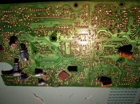
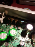
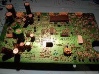
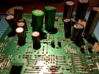
Pictures of current status, already sounds wonderful compared to stock. No need for loudness mode anymore.
Could still use some input with the above questions. Another one is if i should put a 220µF 16V cap on the output of the 7805 reg, all chips should have their own dedicated cap but maybe a cap on the output wont harm with smoothing out.
Got a small problem. When pressing the open/close button it will open half way and then imediately go back in. After quickly pressing the button repeatedly after 5-6 times it does succeed to open all the way. It has always had this issue even pre modification.
Ive already switched the actual switch underneath with a different one from the "number 9" button. Resoldering and checking traces to no avail.So something else triggers the tray to retract early.
Also wondered about replacing OPAMP. Currently has a NJM4560. Google gives so many opinions I am wondering if its even worth it. Any success stories around of people who upgraded this specific OPAMP and only had positive results?
It could be that the controller is detecting a problem while opening. Just like when you push the drawer to close when the motor is triggered to close. If you haven't done this yet, clean everything and check the parts.
Check data sheets before making changes to regulators, they can become unstable.
I have done some of the same things to a few CD players, RC in power, replaced capacitors. What had the most impact was replacing all the carbon resistors between DAC and output with metal type.
Check data sheets before making changes to regulators, they can become unstable.
I have done some of the same things to a few CD players, RC in power, replaced capacitors. What had the most impact was replacing all the carbon resistors between DAC and output with metal type.
Thanks for the input!
Attached is a section of the service manual
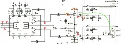
I marked only the left audio channel. After the DAC comes 3302 which is a 10k resistor 3304 which is a 15k resistor.
I plan as advised to exchange these for metal film equivalents. After some research i read good things about the Takman Rey series.
a 10K 0.5w would be replaced by (REY50-090) - 10R 0.5W TAKMAN Metal Film Resistor | Hifi Collective
After that i am not sure how to proceed. i have custom RCA plugs now so i can just wire the signal from anywhere. I planned to connect the RCA straight to output of the 2306 cap ( green line ) and cut the trace after that ( red line ) to avoid interference from the headphone and mute circuit. But can i just avoid resistors 3306 and 3308 like that?
Diodes wise i plan to upgrade 4 PSU ones to the following schottky 11DQ10 Schottky Diode | Hifi Collective
Attached is a section of the service manual

I marked only the left audio channel. After the DAC comes 3302 which is a 10k resistor 3304 which is a 15k resistor.
I plan as advised to exchange these for metal film equivalents. After some research i read good things about the Takman Rey series.
a 10K 0.5w would be replaced by (REY50-090) - 10R 0.5W TAKMAN Metal Film Resistor | Hifi Collective
After that i am not sure how to proceed. i have custom RCA plugs now so i can just wire the signal from anywhere. I planned to connect the RCA straight to output of the 2306 cap ( green line ) and cut the trace after that ( red line ) to avoid interference from the headphone and mute circuit. But can i just avoid resistors 3306 and 3308 like that?
Diodes wise i plan to upgrade 4 PSU ones to the following schottky 11DQ10 Schottky Diode | Hifi Collective
I used VISHAY MBA02040C2200FCT00 because they fit the pitch used on these boards. Also, no long leads connecting the RCA to the board.
My goal was to see if changing parts would be detectable. Changing too many parts and/or the circuit would have made it impossible to come to any conclusion.
I found the datasheet for the diodes used by Sony. The specs looked good so it didn't seem worth it.
My goal was to see if changing parts would be detectable. Changing too many parts and/or the circuit would have made it impossible to come to any conclusion.
I found the datasheet for the diodes used by Sony. The specs looked good so it didn't seem worth it.
- Status
- This old topic is closed. If you want to reopen this topic, contact a moderator using the "Report Post" button.
- Home
- Source & Line
- Digital Source
- My first project : Marantz CD 48 disc not spinning