Remember that the final error waveforms should always be close to zero.
When the light reaching the two diodes is equal, the error signal is minimal... its centred on track. If you increase the gain of the amp stages, the final error signal still has to be the same minimal value.
So don't expect to see the final error signal increase, the gain change will just give the servo enough range to work with to initially get the beam on track. Increasing the gain to much will increase the noise on the error signal while still keeping the fundamental waveform the same.
I'm not so sure you would tbh. That signal is what ultimately drives the tracking coils of the pickup. If that signal were bigger, the lens would move further. If its correct now then it should also be similar after the mod.
The defect on the disc is fixed and so the waveform needed to correct that defect is 'fixed'. Its like a servo system on an amp for DC offset. The error voltage is the same no matter what the internal gain structure of the servo... within limits until the servo loses lock and goes out of range.
You will have to try that and see what happens in practice.
And I tried...
First of all, please ignore the photographs and schematics posted
before, there are some errors. What follows is correct.
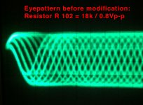
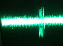
One wrong assumption is the amplitude of the eyepattern. It is 1.2V overall but only 1Vp-p. The schematic from Luxman forgot
the decimal point btw, 12V will definately shorten the laser diode´s
life to less than a picosecond
The second error was R105. I calculated a wrong value by not considering VR101. Many thanks to Mooly for correcting that.
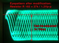
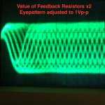
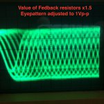
I raised the value of the resistors in the schematics by 1.5.
This resulted in 1.2Vp-p in the eyepattern and the opportunity to lower the level to 1Vp-p as stated in the service manuals.
I made this modification on two BU-1C equipped players today, a Sony CDP-103 and a Sony CDP-302. On both I could lower laser power.
To my very surprise, lowering the power by 0.2V meant just a tiny almost unperceptible counterclockwise turn of VR1,
a 10k trimmer on the BU-1C laser board.
I really wonder how they aligned during production, its like microsurgery.
This could be due to aging, but VR101 for E-F balance has to be reajusted as well, which was easy with a sensible margin.
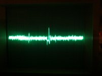
Best to do so is by pressing the search button and to watch the E-F error "peaks". Turn the trimpot until they are symmetrical.
But both players also worked without readjustung E-F balance.
I asked Sam from "Sams Laser FAQ" if the mod was sensible.
His answer was:
There should be no harm in
increasing the PD amplifier gain. At worst it will add noise and make
things worse, but should not damage anything. Don't increase it beyond
the spec'd value. (Which we do not know)
Running just at threshold will not be reliable but I have not heard of
any real risks unless the power regulation feedback becomes unstable.
In general, the laser diode power should be quite constant until
near end-of-life since it's feedback regulated. Only when the diode
cannot output sufficient power at the diode current limit will
regulation fail and the power will decline. Nothing much can be
done on the LD side for that
So running the laser with lesser power will not do any harm?
Not that I'm aware of, at least not in terms of the LD chip itself.
However, as I said, if the regulation becomes unstable, that could
damage it. I do not know if that can happen.
But it is not proven that it´s life can be prolonged as it runs producing lesser heat…?
Well, yes, lower current = lower heat = longer life. But it's not an exact
science.
If the LD regulation circuit isn't maxed out, the diode should be OK since it's
using the actual output of the LD inside the can. That's the test.
Now, in principle, the monitor photodiode response can change. I don't know
if it does though in any significant way over time.
Well, as the slightest turn of the trimmer for laser power resulted in
relatively drastic changes in amplitude. I assume the regulation circuit must have a headroom...
In other words I cannot imagine a circuit that can be maxed out by turning the trimmer just a bit.
But as a result I will put multiturn trimmers in the BU-C for adjusting laser power.
I am not sure whether not changing R109 and R110 (in contrast to an earlier
schmatic) is correct. But I think R108 does the job already.
So if everything is correct now, we could start a new thread and do a database of players using the CX2019, with the feedback resistors original and altered values.
I.e. the CX20109 feedback resistor´s values in a Nakamichi OMS7II/OMS5II CD player (using a KSS-123A laser) are different from a BU-1C.
All the best,
Salar
First of all, please ignore the photographs and schematics posted
before, there are some errors. What follows is correct.
One wrong assumption is the amplitude of the eyepattern. It is 1.2V overall but only 1Vp-p. The schematic from Luxman forgot
the decimal point btw, 12V will definately shorten the laser diode´s
life to less than a picosecond
The second error was R105. I calculated a wrong value by not considering VR101. Many thanks to Mooly for correcting that.
I raised the value of the resistors in the schematics by 1.5.
This resulted in 1.2Vp-p in the eyepattern and the opportunity to lower the level to 1Vp-p as stated in the service manuals.
I made this modification on two BU-1C equipped players today, a Sony CDP-103 and a Sony CDP-302. On both I could lower laser power.
To my very surprise, lowering the power by 0.2V meant just a tiny almost unperceptible counterclockwise turn of VR1,
a 10k trimmer on the BU-1C laser board.
I really wonder how they aligned during production, its like microsurgery.
This could be due to aging, but VR101 for E-F balance has to be reajusted as well, which was easy with a sensible margin.
Best to do so is by pressing the search button and to watch the E-F error "peaks". Turn the trimpot until they are symmetrical.
But both players also worked without readjustung E-F balance.
I asked Sam from "Sams Laser FAQ" if the mod was sensible.
His answer was:
There should be no harm in
increasing the PD amplifier gain. At worst it will add noise and make
things worse, but should not damage anything. Don't increase it beyond
the spec'd value. (Which we do not know)
Running just at threshold will not be reliable but I have not heard of
any real risks unless the power regulation feedback becomes unstable.
In general, the laser diode power should be quite constant until
near end-of-life since it's feedback regulated. Only when the diode
cannot output sufficient power at the diode current limit will
regulation fail and the power will decline. Nothing much can be
done on the LD side for that
So running the laser with lesser power will not do any harm?
Not that I'm aware of, at least not in terms of the LD chip itself.
However, as I said, if the regulation becomes unstable, that could
damage it. I do not know if that can happen.
But it is not proven that it´s life can be prolonged as it runs producing lesser heat…?
Well, yes, lower current = lower heat = longer life. But it's not an exact
science.
If the LD regulation circuit isn't maxed out, the diode should be OK since it's
using the actual output of the LD inside the can. That's the test.
Now, in principle, the monitor photodiode response can change. I don't know
if it does though in any significant way over time.
Well, as the slightest turn of the trimmer for laser power resulted in
relatively drastic changes in amplitude. I assume the regulation circuit must have a headroom...
In other words I cannot imagine a circuit that can be maxed out by turning the trimmer just a bit.
But as a result I will put multiturn trimmers in the BU-C for adjusting laser power.
I am not sure whether not changing R109 and R110 (in contrast to an earlier
schmatic) is correct. But I think R108 does the job already.
So if everything is correct now, we could start a new thread and do a database of players using the CX2019, with the feedback resistors original and altered values.
I.e. the CX20109 feedback resistor´s values in a Nakamichi OMS7II/OMS5II CD player (using a KSS-123A laser) are different from a BU-1C.
All the best,
Salar
Attachments
Last edited:
Thats all great work and very comprehensive. I would agree with the comment on the LD maintaining its output until the very end, that's exactly how the OPC (optical power control) circuit is designed to work.
The current flowing in the laser diode vs lasing action is extremely non linear and that is why you see a relatively big jump in RF for a little change in LD current.
and very comprehensive. I would agree with the comment on the LD maintaining its output until the very end, that's exactly how the OPC (optical power control) circuit is designed to work.The current flowing in the laser diode vs lasing action is extremely non linear and that is why you see a relatively big jump in RF for a little change in LD current.
Hm... if the current vs. lasing action is nonlinear shouldn't it be better to doublle
or triple the value of the RF amps feedback resistors?
There are some (western) numbers / equetations in the japanese CX20109 datasheet
that might help calculating how far amplification can be driven...?
or triple the value of the RF amps feedback resistors?
There are some (western) numbers / equetations in the japanese CX20109 datasheet
that might help calculating how far amplification can be driven...?
Last edited:
No, because although its very non linear it is still rigidly controlled by the optical feedback power control. Remember this setting isn't really to set laser current, its to set a specified optical output from the LD. So wherever it is set, the power control will maintain that value. The current may vary wildly due to temperature change for example, but the light output is constant and so your level of RF and error waveforms remains constant.
Yes still the difference in optical output is just 1/6 less. I will try doubling the feedback resistors value next week.
But the non-linearity explains why in Philips CDM-1 the position of trimmers varies extremely.
They cover amore narrow range than Sony, so setting the current is easier.
But this whole fact of nonlinearity may lead to another idea. Let´s assume
that the Sony circuitries were the dominant ones on the market in the middle eighties
Let´s ´s also assume that setting the laser diode´s current had a very tight margin.
(I did not examine other CX20109 based players) So what might have been reported as weak laser
was probably the laser power set very conservatively in the factory.
Almost all BU-1C based units I own are in the 0.8Vp-p range after cleaning...
And the datasheets allow an Eyepattern of 1Vp-p +/-0.2V
When you ramp up the current in a laser diode you start to see a dull red glow... but that isn't polarised laser light, its simply the LD behaving as a side emitting LED. Only when the current reaches the amount needed for lasing does the light output shoot up massively... the polarised laser light we want as lasing starts... and from that point a relatively small increase in current gives a large increase in light emission.
The Sony pickups have the factory set current incorporated into the serial number on the pickup and so its easy to check if the current has increased (which means a failing diode).
The Sony pickups have the factory set current incorporated into the serial number on the pickup and so its easy to check if the current has increased (which means a failing diode).
Noise is the big problem I've kept mentioning all along. All players will be different in the way they cope with noise and depending how bad it is you could find the error correction working harder and/or jitter increasing. How the player ultimately copes with that is down to each specific design and chipset.
I know. This is why I was testing. But no glitches during playback and quick jumps from track to track as always. Maybe someone else owning a BU-1C could measure jitter and error correction. I think the CX2034 / CX2035 have a pin that goes high when an error correction is triggered. I will only put in 10k precision trimmers for the laser power, as the original ones seem to be rather coarse.
How? No hints in the service manuals... I assume I have to measure over
R3 /22Ω and calculate current from voltage...
The manual for the Esoteric P-700 transport (page 6) does talk about it in detail.
Trouble is, that the resistor is not really accessible and you have to take the bottom cover off, solder some wires across the R22 and then measure the current while CD is playing.
I did not conplicatria the matter. The important thing at the end is the sound, everything is focused on that purpose, the important thing is the DAC, either on CD or external, there will always be a CD and a means of obtaining the input signal to the DAC.
Sometimes we cling to the "iron" and lose sight of the objective "the sound"
In 50 years most of the laser diodes of CD players will be "Kaput" What is the future of the players? In my opinion, none ... what matters is the process of the signal, with indenpendence of the source. Nothing else.
And in 150 years when the stock of vacuum tubes runs out? What will be the future of sound?
..... ????
My ears will be the same, technology will not. sure.
I have stored laser pick-up for my player for the next 100 years (with a replacement every 20 years), I do not worry with 52 years to live another 100 years more. I am worried about the silence after death, because who can live without music?
Last edited:
 Thread re-opened at OP's request.
Thanks! So, after a five years hiatus I woul like to go back to the original idea to amplify the photodiode current.
(Nevertheless, do also take a look at the alternate approach where the input sensitivety of the RF-Amp is raised, see posts #65 and #73)
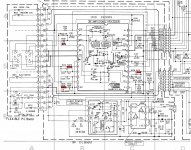
I found the following schematic on the first gen. Nakamichi OMS-5 and 7, using Olympus TAOHS Laser Units.
In this schematic, the current is amplified using 2SC2813 transistor, correct? If so, how much is the ratio?

(Nevertheless, do also take a look at the alternate approach where the input sensitivety of the RF-Amp is raised, see posts #65 and #73)
I found the following schematic on the first gen. Nakamichi OMS-5 and 7, using Olympus TAOHS Laser Units.
In this schematic, the current is amplified using 2SC2813 transistor, correct? If so, how much is the ratio?
Last edited:
- Home
- Source & Line
- Digital Source
- An Idea for saving Laser Life - amplifying the current?