Yes, this method is meant for healthy lasers.
To make them run cooler and last longer. But it would be interesting to
discuss a "healthy" lower threshold. I have not much knowledge on that.
As stated by Mooly the amplification of the laser current has nothing to do with the RF amp
I changed R108 to 180k in the meantime, this seemed to have no
effect; Focus Gain did not change.
Changing the feedback resistors R104 / R105 for EF makes the BU-1C not read the CD. I probably have to re-adjust E-F Balance
R104 and R 105 should not be altered. I could not readjust E-F balance.
Put the original resistors back in and everything worked fine again.
First conclusion, with one question:
Raising R 102 definately helps. This feedback resistor´s opamp
-that amplifies the summed signal from photodiodes A+C / B+D- works relatively independent.
In question is the focus error amp.
I played a bit with focus bias turning VR102 and very quickly went to
non-playability. So It think R109 and R110 should not be touched.
But I am wondering: Why could I change R108 without noticing a difference?
Could it be that because of the low level of the unaltered signal it was alredy a bit off?
So by slightly turning VR102 would I have gotten the sam result as by replacing 120K to 180k @ R108?
Below is the update of the mod.
Attachments
Last edited:
Its all uncharted territory... focus gain and tracking gain have a very wide margin on a good player and the adjustments can be altered a long long way from optimum and the machine still remain playable.
A good reality check would be an official disc with simulated playability errors and to confirm the player still meets the spec for error correction.
A good reality check would be an official disc with simulated playability errors and to confirm the player still meets the spec for error correction.
Yes and no: I use "Digital Recordings CD-Check"
dor testing errors and results vary.
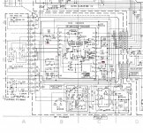
The Bu-1C I am working on is in a Sony CDP-103.
I have no schmatic at hand in this moment.
But the tracking error signal and focus error
signal each pass through a 22k resitor on the main board.
I wonder wether I should lower these 22K resistance by one third
and keep anything else on the Bu-1 -besides R102- unaltered...
dor testing errors and results vary.
The Bu-1C I am working on is in a Sony CDP-103.
I have no schmatic at hand in this moment.
But the tracking error signal and focus error
signal each pass through a 22k resitor on the main board.
I wonder wether I should lower these 22K resistance by one third
and keep anything else on the Bu-1 -besides R102- unaltered...
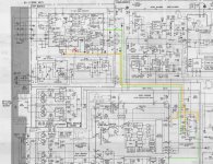
So, what I would like to test next is to keep the feedbeck resistor R102
on the BU-1 Board changed (from 18k to 27k to raise gain by one third) with anything else on the Bu-1 board untouched.
As there is still gain from the focus error and tracking gain amps missing:
I would lower the value of R201 / R203 / R221 on the main board in the Focus Error and Tracking Error lines. Does this make sense?
All the best,
Salar
Attachments
I'm not so sure that would have much effect tbh. You really need to increase TE and TF and that look's possible by altering R104/105 and R108. That looks like it would maintain similar levels or FE and TF is you got the gains correct.
R201 could be lowered to increase FE later down the signal path.
R203 doesn't appear to be a gain setting resistor, its just an input termination for the comparator and also forms a time constant with C202.
R221 would give more signal at the preset if there wasn't already enough range with the wiper at one end.
As I wrote changing R104 / R105 made the disc non-playable. VR101 that is
next to R105 and fixes E-F Balance. It was in the sweet spot with the original resistors
as well as with the altered values. The disc did stop rotating with the altered resistor
values if VR101 was off in both directions...
next to R105 and fixes E-F Balance. It was in the sweet spot with the original resistors
as well as with the altered values. The disc did stop rotating with the altered resistor
values if VR101 was off in both directions...
Last edited:
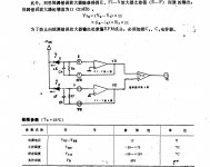
Maybe this excerpt from a japanese CX20109 datasheet - I did not find an english one - helps a bit with the problem of R104 / R105, as "mathematics is the universal language" (from the movie "Contact") Unfortunately I am not proficient in both. Maybe a japanese member chimes in as well.
But I assume this excerpt shows the role of the parallel capacitors C102 / C103.
And if the values I proposed earlier are correct or not..
But I assume this excerpt shows the role of the parallel capacitors C102 / C103.
And if the values I proposed earlier are correct or not..
Attachments
Ah, this is a transimpedance amplifier. Could anyone help me doing the math?
I want to raise output by one third (R104 / R105) and adapt the capacitors (C102 / C103).
I know there is formula on the web, but again, a language I am not proficient in.
https://www.diyaudio.com/forums/att...ng-current-bu-1c-schematic_altered_values-jpg
I want to raise output by one third (R104 / R105) and adapt the capacitors (C102 / C103).
I know there is formula on the web, but again, a language I am not proficient in.
https://www.diyaudio.com/forums/att...ng-current-bu-1c-schematic_altered_values-jpg
Perfect, thanks! If you succeed to calculate the correct values
for R104 / R105 and C102 / C103 (output gain has to rise by one third)
the can of worms you mentioned will spread over 70% of the
players from that time using the Sony CX20108 / Cx20109 / CX23035 chipsets:
Accuphase, Aiwa, ADC, Adcom, Akai, Audioanalyse, Blaupunkt, Denon, Dual, Emerson, Funai, Hitachi, Kenwood,
Metz, Nakamichi, Nec, Pioneer, Sanyo, Schneider, Shure, Sony (of course), TEAC, Telefunken, Vector.
You could add a series resistor to make it a conventional inverting voltage stage but then you are into deteriorating the signal with noise... whether that would matter I don't know.
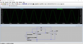
Photo diodes are usually run into a transimpedance stage to maximise the bandwidth due to the diode capacitance
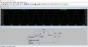
The transimpedance stage works like this.
If the current source (photodiode) generates 100uA of current, the voltage at the opamp output will be that value of voltage needed to generate the same 100uA of current in the feedback resistor.
Both traces are overlaid on each other. Right hand scale shows 100uA peak current from the diode, and the left hand shows the opamp output voltage which is 0.1v peak.
0.1 volts across 1k (the feedback) means 100uA peak flows in the resistor.
Make the resistor 5k and now we need 0.5 volts at the opamp output to maintain that 100uA in the feedback.
The small caps will aid stability although the exact effect they have depends on the dynamic characteristics of the photodiode but as a general rule you would decrease the cap in line with increasing the feedback.
To increase the output by a set amount just substitute a fixed value of 'I_Diode' such as 100uA. Look at what value the resistors are (the fixed one) and calculate the voltage that would be needed at the opamp output to give that.
For example if R was 6954 ohms then we know that V=I*R and so the opamp must be giving 100uA * 6954 which is 0.696 volts. If you wanted to increase that to say 1.1 volts then you need R=V/I which is 1.1/100E-6 which is 11k
The current may be much smaller than 100uA but it doesn't matter because the ratios are correct, even if you calculated a million volts output.
Attachments
Dear Mooly, thanks! But frankly a basic explanation is just too complicated and
simply too time consuming for me in the moment.
All I need now (I can learn the basics later) is a proposal to which value R104 / R105 // C104 should be changed to get a rise in gain by about one third. This is why I posted the CX20109 Datasheet.
I now have the time for the next two hours to buy the resistors / capacitors needed and to try them tonight. All the best,
Salar
- Home
- Source & Line
- Digital Source
- An Idea for saving Laser Life - amplifying the current?