Saving Laser Life by Amplifying the Photodiode´s Current?
I tried to swap a sharp LT022MC Laserdiode in a Sony BU-1 transport with no success.
Besides aligning the biggest problem is that replacement diodes on the market are junk. Bought 28 of them, 26 were defective.
I will try a replacement with a contemporary Rohm diode, but this can be only done with experinced help, see this thread:
Dead Laser Pickups - why not replacing the Diode only?
Now, another idea:
Voltage p-p of the eyepattern in early Sony players (as well as many others) was 1.2V.
The ones I own are between 1V and 0.8V after 30 years
To save laser live: Why not putting the output down close to threshold current
and amplifying the current of the photodiodes before it is sent to the RF-Amp?
Threshold curent and operating current are close but in my case it looks like
I can halve syepattern´s p-p close to 0.5V before the player fails
Would this save laser live? I have read somewhere that running a laser
in it´s lower emitting limit could be harmful as well -
but I do not recall the source in the moment as well as its credibility...
I also do not know if beam divergence is influenced by this.
But for the moment, a good idea to follow?
All the best,
Sal
Last edited:
Although the recovered RF may be down in amplitude after 20-30 years, it doesn't automatically follow that low emission of the LD is the primary cause. Atmospheric contamination of the internal optics plays a big part here.
Early Sony players have the LD current marked on the pickup and this figure can be used to gauge deterioration. The condition of the optics is irrelevant for this check as the LD's optical output is monitored by an internal photodiode on the same die as the LD chip. If its increased by around 10% or more then the diode is impaired/deteriorated.
The threshold current is extremely temperature dependent and like most things, the original settings will be decided primarily by long term reliability in all user conditions.
Noise is the big problem in looking to amplify a lower base photodiode current, much like a minimum field strength is needed for good RF reception with an aerial and why using a smaller aerial with amplification is no good.
I have dismantled a BU-1 with a. 0.8V output and cleaned the objective lens,
collimating lens, polarisation prism, diffraction grating, laser window.
Besides the usual dirt on the objective lens, the Q-Tip remained clean
on the other parts. It is said in a forum for portable CD players, that the coating of the laser of the first portable player D-5 ages. I do not know wheter this is the same with the BU- built the same time but I doubt.
So how do I correctly measure the photodiode´s output in relation to the laser diode. As far as I remember, the service manuals do not cover this issue.
I also hae aleader laser power meter. I assume, optical output power is measured by placing the probe directly on the hexagonal cover?
The window for measuring the emitted light is recessed about 1mm - so I assume this is the sweet spot for measuring as sthis is the distance of the CD...?
Deterioration of coated optics would not alter the current vs optical output of the LD as measured within (which you can't do) the diode itself. The clue would be an increase (or not) of the LD current compared to the value marked on the individual pickup.
You are assuming the LD is deteriorated and low in emission but you don't know that for sure.
I've never heard of the coating on the LD itself deteriorating tbh although I do know Sony issued a bulletin over hygroscopic objective lenses looking milky. They would clear and return to normal once the player was in use as presumably the heat dried them out fully.
The power meter was always intended to measure the optical output from the objective lens rather than the LD itself... and I've used these myself in the past and found them to be of little use tbh.
At the end of the day, if the RF is low and causing problems then you have to fix by whatever means is appropriate such as pickup replacement.
The idea of amplifying the photodiodes has not been
discussed yet. Laser life is much dependent from the
on the heat generated. So let's assume I want to run a diode
as cool as possible above the threshold current-
what transistors could be used to amplify the current of the photodiodes?
discussed yet. Laser life is much dependent from the
on the heat generated. So let's assume I want to run a diode
as cool as possible above the threshold current-
what transistors could be used to amplify the current of the photodiodes?
The output from each of the main (four) photo diodes becomes a voltage at the output of the transimpedance amp. One transimpedance amp for each photo diode. These four individual voltages are summed to give the RF signal which is then a voltage. That is what you measure when you look at the 'RF' or eye pattern, it is the summed output of the photo diode array.
Thanks! But I think you left out that the original RF amp has to be taken into consideration or I misunderstood you.
I attached a typical circuit of the BU-1. The eyepattern is created by the RF-Amp which also provides the servo signals.
Idea is to lower the laser´s output power to prolong it´s life and and in return amplify the signal / current before the RF amp by the same amount so the RF Amp sees a signal at the desired level. As you can see, the photodiodes are tied together, A+C an B+D.
E+F must be amplified as well
All the best,
Salar
Attachments
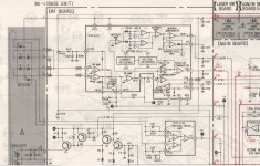
The first two opamps marked RF Amp in the chip are the transimpedance amps. There is no measurable voltage at their inputs because they are configured in a virtual ground arrangement.
Transimpedance amplifier - Wikipedia
A/B/C/D/ are the four photodiodes I mentioned.
The third RF Amp is a standard inverting voltage amplifier stage (a virtual ground mixer) that combines the output of the two RF amps to give the familiar eye pattern.
The side spot detectors also go to their own transimpedance amplifiers and the output of these is then fed to a differential type stage to obtain the tracking error signal.
If you reduce the laser current you also reduce the current produced by the photo diodes. That in turn reduces the final I/V conversion result and so the voltage output of that third opamp is lower, and the same applies for the tracking error signal.
Although you could increase the gain of the third opamp stage and add gain to the tracking error output it would be less than optimum. The designers will have chosen the best ratios for satisfactory operation over a wide range of conditions.
By all means experiment but also accept that you wont end up with as robust a player that would meet its playability specs under all conditions.
Hello Mooly, thanks for your detaild reply but this was not the basic question of this thread and i never intended to play around with the existing RF-Amp.
The question was:
How - this means by which circuitry- can I raise the current of the photodiodes before they are fed into the RF Amp?
I assume some low noise transistors could work...?
All the best,
Salar
The question was:
How - this means by which circuitry- can I raise the current of the photodiodes before they are fed into the RF Amp?
I assume some low noise transistors could work...?
All the best,
Salar
The current the diodes produce is fixed and proportional to the illumination they receive.
If you try and amplify the diode output (its voltage output) by transistors then you are going to run into noise issues. You would then have to mix the signals in the same way the chip does. You could try making an opamp I/V convertor with higher gain which would in practice be the same as in the chip, just with a higher feedback resistor wrapped around each opamp.
To try and make a transistor discrete I/V convertor for this would almost certainly be very inferior to using dedicated opamps.
R102 on your circuit looks to set the voltage gain of the final RF stage. You could alter that to increase the RF level to compensate for a lower LD current but signal to noise ratio of the eye pattern will deteriorate. You also have to make sure the side spot detectors generate the correct amplitude tracking error signal so you would need to add gain to the TE signal.
Be very careful. The photodiodes are the most static-sensitive element in a CD head; playing with interposing an amplification stage is highly likely to kill an otherwise working, if aged, CD pickup.
If the player is old enough to have tracking, focus and laser power adjustment potentiometers, find a manual and re-set to the recommended settings while monitoring the eye pattern.
If it is newer than that, all the above are actually 'servo controlled' by the relevant chip/dataslicer (e.g. for Philips mechs CDM9 or newer / SAA7310 and later). Nothing to play with there....
Hello Martin,
you do not mistake the laserdiode for the photodiode, do you?
Because when a new laser head was /is shipped, the laserdiode is the
part that is short circuitred with a blob of solder. Never saw this
extra ESD protection with the monitordiode or the photodiodes.
Please take also into consideration that this thread is not about the usual
aligning process. It is only about the technical possibility to amplify the current
from photodiodes that get lesser light from a laser diode that deliberately runs
with less power in order to lenghten it´s life.
The current does not need to be amplified that much btw, just doubled…
Probably this could have been a part of the aligning proces if the designers
of the RF-Amps would have allowed the I/V conversion to be adujusted externally…
Maybe they did this in an alternate universe or early laboratory designs")
What About R102, R104, R105, R108 and R109 in the schematics posted the page before?
Can the output of the opamps be raised? Same result…?
you do not mistake the laserdiode for the photodiode, do you?
Because when a new laser head was /is shipped, the laserdiode is the
part that is short circuitred with a blob of solder. Never saw this
extra ESD protection with the monitordiode or the photodiodes.
Please take also into consideration that this thread is not about the usual
aligning process. It is only about the technical possibility to amplify the current
from photodiodes that get lesser light from a laser diode that deliberately runs
with less power in order to lenghten it´s life.
The current does not need to be amplified that much btw, just doubled…
Probably this could have been a part of the aligning proces if the designers
of the RF-Amps would have allowed the I/V conversion to be adujusted externally…
Maybe they did this in an alternate universe or early laboratory designs
What About R102, R104, R105, R108 and R109 in the schematics posted the page before?
Can the output of the opamps be raised? Same result…?
Last edited:
Those resistors would alter the gains and it may well work and play but it can't be optimal. (R109 isn't a gain setting resistor)
Its like saying that if we cut vinyl discs with less groove modulation then we can make up the difference with a higher gain RIAA preamp. The downside is reduced signal to noise ratio.
Its like saying that if we cut vinyl discs with less groove modulation then we can make up the difference with a higher gain RIAA preamp. The downside is reduced signal to noise ratio.
I checked some CX20109 RF-amp circuits today.
A BU-1C, a Sony CD-40 with an ordinary worm drive and a belt driven Nakamichi OMS-5II.
The (feedback) resistors of the Sony CX20109 circuits are the same, in the Nakamichi they differ.
The Nak uses a Sony KSS-123A Head, the Sony CD-40 uses a KSS-120.
So it looks like the CX20109 has been been built for versality.
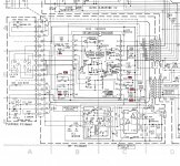
I am a layman with opamps, but tried to change the values -theoretically-
of the resistors surrounding the opamps, mostly feedback resistors.
The idea is to raise the output power of the opamps in the CX20109 by one third.
I have a BU-1C where the amplitude of the eyepattern is down to 0.8V p-p instead of 1.2Vp-p
So this BU-1 with an aged laser diode would be a candidate to see if the mod may work.
But before staring soldering, someone could take a look on the values
I altered in the attachment below?
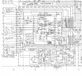
As far as I know, there are no schematics of the BU-1C available from Sony,
where the resistor values are noted. I do not know why the values are missing in the service manuals of the CDP-102/103/302/502
But I found the service manual of a Luxman D109, where the values are noted.
So the first attachment (BU-1C Schematic) shows the BU-1C circuit unaltered, some people might need it for other purposes.
In the second attachment (BU-1C Schematic_Altered_Values) I added the altered values in red. Maybe someone might be so kind to take a look and give a comment.
I am confused how to deal with the circuitry around in 14 (FE+) I assume I can simply raise the offset voltage at VR102 about 1/3 without altering R109 / R110?
All the best and thanks,
Salar
A BU-1C, a Sony CD-40 with an ordinary worm drive and a belt driven Nakamichi OMS-5II.
The (feedback) resistors of the Sony CX20109 circuits are the same, in the Nakamichi they differ.
The Nak uses a Sony KSS-123A Head, the Sony CD-40 uses a KSS-120.
So it looks like the CX20109 has been been built for versality.
I am a layman with opamps, but tried to change the values -theoretically-
of the resistors surrounding the opamps, mostly feedback resistors.
The idea is to raise the output power of the opamps in the CX20109 by one third.
I have a BU-1C where the amplitude of the eyepattern is down to 0.8V p-p instead of 1.2Vp-p
So this BU-1 with an aged laser diode would be a candidate to see if the mod may work.
But before staring soldering, someone could take a look on the values
I altered in the attachment below?
As far as I know, there are no schematics of the BU-1C available from Sony,
where the resistor values are noted. I do not know why the values are missing in the service manuals of the CDP-102/103/302/502
But I found the service manual of a Luxman D109, where the values are noted.
So the first attachment (BU-1C Schematic) shows the BU-1C circuit unaltered, some people might need it for other purposes.
In the second attachment (BU-1C Schematic_Altered_Values) I added the altered values in red. Maybe someone might be so kind to take a look and give a comment.
I am confused how to deal with the circuitry around in 14 (FE+) I assume I can simply raise the offset voltage at VR102 about 1/3 without altering R109 / R110?
All the best and thanks,
Salar
Attachments
Its very much a case of trial and error. If you bring the gains of the front end up then I wouldn't have thought you need alter things after that point because the levels should be back to original values.
The CX20109 was as I recall used in the first original Sony Discman MK1.
The CX20109 was as I recall used in the first original Sony Discman MK1.
The CX20109 was used everywhere between 1984 to 1988 as long as Sony supplied the electronics. From Sony's own Discman (called D-5 respectively D50 btw) to High End (Accuphase - DP 80)
What about R109 / R110? A voltage is led to the positive input of the focus error amp,
I assume they do not need to be changed?
What about R109 / R110? A voltage is led to the positive input of the focus error amp,
I assume they do not need to be changed?
Last edited:
- Home
- Source & Line
- Digital Source
- An Idea for saving Laser Life - amplifying the current?