Hi, I know this is old stuf business but I want to experiment with this option.
Where should I connect a direct isolated 2,5V supply line to feed the existing crystal on a Marantz CD-42 player? I've read in another thread that crystals can get a direct, isolated DC supply providing signigficant sonic improvement.
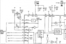
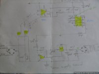
Here below is attached the schematics of the CD-42 showing the original clock circuit. I'm a bit confused of what is the function of Xin & Xout pins on SAA7350 DAC, in terms of voltage supply. I have built an external power supply for this rail. I did some measurments along 3645 - 1K resistor found, 2,25V at the chip side (pin 15) and 2,30V the crystal side. Pin 14 @ 2,20V
Should then needed to remove any part (resisistor) around the crystal circuit? Thanks for your advice
Where should I connect a direct isolated 2,5V supply line to feed the existing crystal on a Marantz CD-42 player? I've read in another thread that crystals can get a direct, isolated DC supply providing signigficant sonic improvement.
Here below is attached the schematics of the CD-42 showing the original clock circuit. I'm a bit confused of what is the function of Xin & Xout pins on SAA7350 DAC, in terms of voltage supply. I have built an external power supply for this rail. I did some measurments along 3645 - 1K resistor found, 2,25V at the chip side (pin 15) and 2,30V the crystal side. Pin 14 @ 2,20V
Should then needed to remove any part (resisistor) around the crystal circuit? Thanks for your advice
Attachments
Feeding a DC supply to a crystal will achieve nothing whatsoever, apart perhaps from crystal damage if the DC is too high.
Xin and Xout pins are the input and output pins for the crystal oscillator invertor in the DAC chip. You don't need to worry about what their DC voltage is, unless you are fault-tracing; it will probably be about half the chip supply rail voltage. They are connected to a tuned circuit consisting of the crystal and a couple of capacitors, with a bias resistor too. This is the standard crystal oscillator circuit used in many digital items: invertor, crystal, a couple of caps and some resistors for bias.
Maybe you are getting confused about the difference between a crystal and a crystal oscillator?
Feeding a DC supply to a crystal will achieve nothing whatsoever, apart perhaps from crystal damage if the DC is too high.
Maybe you are getting confused about the difference between a crystal and a crystal oscillator?
Probably yes. I've checked the operation of crystals that work with a voltage dc or alternate, which resonate them by creating distortion on their plates. When the applied voltage stops (probably due to a feedback operation coming from oscilator), crystal recovers it's shape and as a result this creates a self voltage across it's taps sensing the in of the oscilator
The principle over the clear DC line is based is to isolate the power suppliy from the noise created by the crystal itself , contaminating power lines of DAC and other important chips.
What if I set up a divider in place of 1k , let's say 470+ 470R where at the junction of those resistors to connect the new isolated line (2,30V) and also interupt the loop to pin 15 with a small cap , ie 5pF . This will isolate the DC supply from oscilator to the crystal but would akso allow the AC feedback to flow though the cap to the OSC . Does it make any sense ?
It doesn't make any sense to me.
You would probably just stop the oscillator because you have removed its dynamic driving voltage from the chip. The crystal is just placed across what is little more than an invertor to form the basic oscillator. Connecting to a low impedance 2.5 volt supply will shunt the feedback signal completely.
You would probably just stop the oscillator because you have removed its dynamic driving voltage from the chip. The crystal is just placed across what is little more than an invertor to form the basic oscillator. Connecting to a low impedance 2.5 volt supply will shunt the feedback signal completely.
Perhaps it's loose wording, they must have meant an external crystal oscillator. These usually benefit from a clean power supply. If you use an external crystal oscillator, you should remove all components around Xin and Xout, and feed the output of the oscillator to Xin.I've read in another thread that crystals can get a direct, isolated DC supply providing signigficant sonic improvement.
It must be an XO we are talking about. That needs a clean 5V PSU when the SAA also has 5V supply. Remove all parts except the 1MOhm resistor and connect the output of the XO with a 47 Ohm resistor to the XI pin. I recall having problems when the 1 MOhm resistor is removed (this is the case with certain Philips chips).
I've read in another thread that crystals can get a direct, isolated DC supply providing signigficant sonic improvement....
Can you link to this other thread so that we can see what is being discussed
")
Can you link to this other thread so that we can see what is being discussed
Hi, this is the trhread where it 's been discussed about by Pete (Chivyp) in 1st and 2nd page
Marantz CD42 repair and mods
cheers
No crystal works from DC. All crystal oscillators work from DC. You are confusing the two quite different issues. This may be caused partly by others also being confused or lazy and calling a 'crystal' something which is actually a crystal oscillator. Once you understand the difference you will know why your original suggestion makes no sense at all.andypap said:I've checked the operation of crystals that work with a voltage dc or alternate
Hi, this is the trhread where it 's been discussed about by Pete (Chivyp) in 1st and 2nd page
Marantz CD42 repair and mods
cheers
Thanks.
So (and this is just my opinion), what I think is happening is that the oscillator still manages to free run on its own (such is nature of CMOS invertor type oscillators), and that having the crystal still connected at the invertors input terminal is sufficient for the oscillator to 'lock' to the crystals frequency.
In other words its working by accident rather than design, and almost certainly in absolute terms, the oscillator signal quality will be inferior to the correct connection method.
It may well sound 'different' because of the added jitter/hash/noise of the modified clock signal and that difference may be interpreted as more pleasing.
At the very least you should use a scope to look at the oscillators output signal and compare it to the normal connection. You should also measure the frequency because it may be off a little as the crystal is pulled away from its primary resonant mode by the non conventional circuit.
In the linked thread:
Completely bonkers! But very lucky.
That advice can only come from someone who has no idea about electronics (in particular, no idea how an oscillator works) but turns out to be very lucky in that ruining the circuit somehow does not stop it from working after a fashion. It is reasonable to assume that the correct circuit will work better than the wrong circuit. Increased jitter is a likely result; also some small change in frequency, although that doesn't matter too much. A drift in supply rail voltage or temperature could stop it working altogether.Chivvyp said:As a cheaper alternative to a cheap clock.....
I've found good improvements on some players just by disconnecting the clock out feed from the chip to the std crystal and feeding a clean isolated power supply to the crystal instead. I guess by the time the standard 5v feed (or whatever is used) is routed through and out of the chip it's pretty polluted. With a cheap lm317 reg you get quite an improvement for next to nothing.
Completely bonkers! But very lucky.
In the linked thread:
That advice can only come from someone who has no idea about electronics (in particular, no idea how an oscillator works) but turns out to be very lucky in that ruining the circuit somehow does not stop it from working after a fashion. It is reasonable to assume that the correct circuit will work better than the wrong circuit. Increased jitter is a likely result; also some small change in frequency, although that doesn't matter too much. A drift in supply rail voltage or temperature could stop it working altogether.
Completely bonkers! But very lucky.
Thanks for you input. I have just a couple of questions to clarify some terms.
An external XO is a crystal oscilator by means a standalone component (or circuit) that includes both the oscilator and a crystal rezonator. Do I get it correct? Where should the output of the XO be connected? Can this feed the Xin of a DAC chip? It supposed that Xin is the input of the internal oscilator of the DAC chip. Is it then correct to feed the output of one oscilator (XO) to the input of another oscilator (Xin) ? Somehere over here I loose it a little..Moreover If I well understand, the SAA7350 does not use the master clock output (Xsys) directly, it is just generatinge it in a stand alone internal circuit and thus provide the clock signal to feed the other chips, like decoder SAA7310, SM5840 digital filter and the digital output PCF3523, whiles receiving indirect the clock signal through BCK/ WCK inputs. is it correct?
Yes, an external oscillator can feed the Xin pin. Xin is the input to the invertor used to provide gain for the built-in oscillator, but can also be used as an input for an external oscillator. With no crystal etc. attached, the invertor is no longer part of an oscillator circuit.
In some cases adding an external oscillator will increase jitter, even if the external oscillator has low jitter. The connection adds jitter due to things like poor termination and ground bounce. OK if the extra oscillator is designed in to a PCB by an expert in mixed-signal design; not OK if it is just slapped on by anyone else.
In some cases adding an external oscillator will increase jitter, even if the external oscillator has low jitter. The connection adds jitter due to things like poor termination and ground bounce. OK if the extra oscillator is designed in to a PCB by an expert in mixed-signal design; not OK if it is just slapped on by anyone else.
The connection adds jitter due to things like poor termination and ground bounce. [/QUOTE]
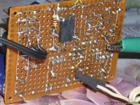
I will experiment with some cmos oscilators I 've seen in mouser.
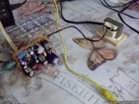
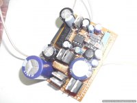
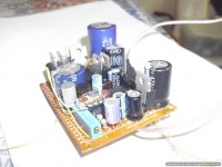
I will make use of the power supply created for the clock. This one designed to have isolated AC supply, 2 stages of series regulators, very high impedance, choke filtering and divided ground terminals. I;m curious of how it's going to perform .
I will experiment with some cmos oscilators I 've seen in mouser.
I will make use of the power supply created for the clock. This one designed to have isolated AC supply, 2 stages of series regulators, very high impedance, choke filtering and divided ground terminals. I;m curious of how it's going to perform .
Attachments
As I said, you could make a perfect oscillator and still get jitter by the way you connect it. Anyway, the important thing is to test it and see. If you get less jitter then you have improved things; if more jitter then you have degraded things. If you cannot measure jitter on your DAC output then you will never know.
Last edited:
Waste of time & money. I fitted a 11.2896 low jitter clock module to my Marantz Cd65 and heard no difference whatsoever.
There are better ways to improve the sound such as the opamps.
Yes, you are absolutely right .
Opamps have already been replaced with the AD8066 (fet input), that were laying spare around. The upgrade was tremendous against the stock 2114D that are really craps. The AD's are getting a bit hot, running at the stock +-15V whilst they have a top working voltage at 12V. One of the first mods was also to remove the filter SM5840 and set the signal NOS. Although sound is well improved still have a missing melody connection , a bit light weight with a losy timing. If I get it right this DAC is a bit overcolored in the mid band (probably higher armonic distortion), but I have not the equipment to measure it. In general it is a good player. I have spent hours of modyfictions to the Philips CD951 with CDM 9 driver and SAA 7350 + TDA1547 DAC chipset, but cd42 bit it easily with basic upgrades only. It also bits the Marantz CD56 with the so called TDA1541.
It depends on the actual implementation. For example the master clock might have low jitter indeed, but the I2S signal (actually the BCK) at the input of the DAC could become spoiled after the digital filter. Best is to have the BCK reclocked directly from MCK, using a really simple and fast reclocker directly at the DAC chip input. That makes a difference.Waste of time & money. I fitted a 11.2896 low jitter clock module to my Marantz Cd65 and heard no difference whatsoever.
There are better ways to improve the sound such as the opamps.
- Status
- This old topic is closed. If you want to reopen this topic, contact a moderator using the "Report Post" button.
- Home
- Source & Line
- Digital Source
- Need advise to supply a clean DC line to a Marantz CD-42 crystal