Q203 is the main +5 volt series pass transistor. If there is 5 volts on the collector then its probably OK. The scope should show a clean 5 volts with minimal noise and ripple (<50 mv pk/pk)
Sorry, my bad, Q203 is ok, it's Q202 that is gone. The ripple I see on the scope is about 30mv pk/pk. The +7v is clean as well according to those standards.
All I can do now is replace Q202 and go again from there. Should I try to get a 2SD774 or is there something more common that I can replace it with ? I won't be able to check if I get a signal before I restore the -5v rail.
If you touched up components in the servos (assuming they are analog) or pick up related electronics you may need to clean off flux residue.
I didn't touch anything on the servo board.
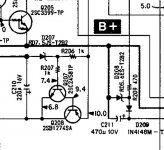
D208 and D209 are shorted which puts pin 1 of Q341,342 and 343 at 0v instead of 5.2v and also pulled the 10v rail down to ground through R209 explaining the 1.4v drop.
D209 is a 1ss120, can I just replace this with a regular 1N4148 ? And D208 is a RD5.6ES zener, I guess a regular 500mW 5.6v zener will do here.
D209 is a 1ss120, can I just replace this with a regular 1N4148 ? And D208 is a RD5.6ES zener, I guess a regular 500mW 5.6v zener will do here.
I replaced the 2 diodes, got the +5.2v back on the emitters of Q241 ~ Q243 but the outputs are still dead silent. I'm lacking the +4.7v on the bases of Q241 and Q242. On the other hand on pin 68 of IC301 labelled as "Mute" I have 4.2v where the schematic indicates 0v, same on pin 28 of the system control IC401.
Whether the mute is working or not, you should have audio on the outputs of all those opamps.
The muting circuit is simple and yet complex in what it does... probably in order to comply with original Red Book standards regarding multilingual and data discs.
All those mute transistors need -5 volts on the base to unmute. You need -5 volts on the collector of the three 'digital transistors' below the opamps. If any of those lines are at +5 then the appropriate mute transistor will be active.
I don't seem to have audio at all, but that might be explained by the fact that some of the voltages still seem wrong.
I have +5v ont all 3 collectors, they each are fed through a 100k resistor (they measure ok). On the other side of those resistors I do have -5v. It looks like those 3 muting transistors are dead as well, or at least 1 of them. I don't know what happened but it sure did some damage.
I have +5v ont all 3 collectors, they each are fed through a 100k resistor (they measure ok). On the other side of those resistors I do have -5v. It looks like those 3 muting transistors are dead as well, or at least 1 of them. I don't know what happened but it sure did some damage.
I seem to have an almost short from the -5v rail to ground when I plug in the power cord but the cd player switched off, when I pull it out again the short (.02v on diode test) stays for a second then moves up to .8v on diode test mode like a cap charging. But that might just be due to the on/off switch circuitry.
And q241 ~ q243 test good.
And q241 ~ q243 test good.
Last edited:
Plus 5 on the collectors of those three 'digital transistors' means it is in mute but that alone would not stop audio being present on the opamp output pins. You can not test those transistors on a meter but I would be surprised if any were faulty.
For all three collectors to be at +5 means that you should be seeing zero volts on pins 11 and 12 of IC 304 and also zero volts on pin 68 of IC301.
If the -5 volts is OK when the player is on then it is fine... don't worry about the 'short', it will just be the meter giving incorrect results due to residual charge on the rail.
If the disc is spinning correctly and the time counter and display is working correctly and advancing normally then it doesn't look good tbh. Its quite possible that whatever happened to cause the initial damage has also damaged some of the processing circuitry somewhere (the IC's).
I do have 0v on pins 11 and 12 of IC304 but 4.9v on pin 68 and it drops to 4.2v when I press play.
That's what I am afraid of as well, display and counter are ok, disc spins alright, I can skip, fast forward, everything seems to work there. I do have the right voltage on pin 71 of IC301 called Data but on pin 34 also called data I have 0v where there should be 2.5v. I suppose that means that the information gets lost somewhere in IC301 . Or could that be due to the 4.2v on the mute pin ?
That's what I am afraid of as well, display and counter are ok, disc spins alright, I can skip, fast forward, everything seems to work there. I do have the right voltage on pin 71 of IC301 called Data but on pin 34 also called data I have 0v where there should be 2.5v. I suppose that means that the information gets lost somewhere in IC301
. Or could that be due to the 4.2v on the mute pin ?
Last edited:
The thing is, there is still more wrong with this than just the final mute circuit because no matter what is going on there, you should be seeing audio on the opamps.
Any data and clock lines will need a scope to confirm activity and that the levels swing between 0 and 5 volts. Service manuals aren't always correct on marked voltages, or they are taken under specific conditions. 2.5 volts sounds spot on and is an average between 0 and 5 and so just what you would expect to see with fast moving serial data.
The mute line dropping to 4.2 volts doesn't sound good. That suggests a zapped port on one of the IC's, either pin 68 or pin 28 of the system control chip. You could try forcing it low and see what happens but beyond that its looking like a zapped chip.
Isn't it possible that the output of IC301 is muted so that the signal doesn't even get to the audio amps ?
test point 1 on pin 41 of IC301 isn't a perfect square wave on the scope, point 2 and 3 are and the efm is good as well. Data output of IC301 is at 0v.
It also seems that pin 68 (Mute) and pin 70(Reset) are shorted, would that mean that IC 301 is indeed zapped. By forcing it to low do you mean clamping it to ground ?
This chip seems to be out there for sale (hard to know if they are genuine) could it be replaced ?
- Status
- This old topic is closed. If you want to reopen this topic, contact a moderator using the "Report Post" button.
- Home
- Source & Line
- Digital Source
- Sony CDP 591 recognizes disc but doesn't play