Hi!
I think I have done something wrong somewhere! I picked up a sony cdp 591 for 5€, it was said to be working but skipping a lot. On my first try it did detect the disc and read without much trouble but skipped a lot. I opened it up and the laser was very foggy, I cleaned it with some alcohol and that did the trick, no more skipping. Now I saw some pretty bad solder joints so I decided to get the board out and reflow the joints that were dry or cracked, put the thing back together but now when I put in a disc it detects it, shows the number of tracks and total time but when I press play it starts up, shows track 1 0:00 and then there's a little click, display shuts down, laser gets back down and it starts all over again and again and again... looks like the whole player just shuts down just before it actually starts reading. It sounded familiar to a problem on my rega planet on which changing the rectifier diodes repaired this problem but not here. I checked my solder joints and nothing touches that shouldn't touch, does anyone know where I might have done something ?
I think I have done something wrong somewhere! I picked up a sony cdp 591 for 5€, it was said to be working but skipping a lot. On my first try it did detect the disc and read without much trouble but skipped a lot. I opened it up and the laser was very foggy, I cleaned it with some alcohol and that did the trick, no more skipping. Now I saw some pretty bad solder joints so I decided to get the board out and reflow the joints that were dry or cracked, put the thing back together but now when I put in a disc it detects it, shows the number of tracks and total time but when I press play it starts up, shows track 1 0:00 and then there's a little click, display shuts down, laser gets back down and it starts all over again and again and again... looks like the whole player just shuts down just before it actually starts reading. It sounded familiar to a problem on my rega planet on which changing the rectifier diodes repaired this problem but not here. I checked my solder joints and nothing touches that shouldn't touch, does anyone know where I might have done something ?
I have reported that in the very same thread
good to know.
Well, the schematics are really bad quality, I checked the obvious +/-5v +/10v -30v and the +7v rails and they are all there but it's hard to read the rest. Some other stuff that might help someone point me in the right direction, the little led on the volume potentiometer also goes out when the laser resets (all the voltages stay on track) and when I go to track 8 or whatever and press play, the block always return to its initial position before trying to play. I can also fast forward and backwards normally but again, when I press play it returns to its initial position and starts at 1 again.
The led is connected to the +5v rail and then through a resistor to pin 27 on the system control IC which should be at 0v and it is, when the led goes out, at the same time as the laser resets and the display goes out (all just for a split second) pin 27 jumps to about 4v. The +5v rails stays steady but I guess that the fact that it is for just a very short time could mean that it is just compensated by the filter caps.
It was worth a try to look at the LED. I didn't realise it was driven from the syscon, I thought it was illuminated all the time.
So is the headphone hum another possible clue ?
The headphone amp input is taken from the main line output and is under control of the muting transistors which is probably why the hum disappears in pause and stop mode.
I scope the -/+5 volt rails at the line output stage.
Also check for clean 5 volts on Q209 emitter and a clean 7 volts on Q208 collector.
It is illuminated all the time but the 0v still is on the control chip.
Q203 appears dead, it reads open base to collector so I can't test any further for now.
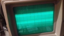
The +5v rail gives me this reading on the scope :
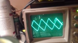
And this is on the 7v rail :
+/- 10v gives me the same result as on the +5v rail. also I can't seem to pick up the signal on the output of the DAC.
Q203 appears dead, it reads open base to collector so I can't test any further for now.
The +5v rail gives me this reading on the scope :

And this is on the 7v rail :

+/- 10v gives me the same result as on the +5v rail. also I can't seem to pick up the signal on the output of the DAC.
Q203 is the main +5 volt series pass transistor. If there is 5 volts on the collector then its probably OK. The scope should show a clean 5 volts with minimal noise and ripple (<50 mv pk/pk)
The 7 volt rail (Q208) should be similar for noise and ripple.
The outputs of opamp IC306 are where you will pick the audio signal up.
Make sure you are using the correct power supply ground points.
The 7 volt rail (Q208) should be similar for noise and ripple.
The outputs of opamp IC306 are where you will pick the audio signal up.
Make sure you are using the correct power supply ground points.
If you touched up components in the servos (assuming they are analog) or pick up related electronics you may need to clean off flux residue.
The fact that the fuses blew is a pretty clear indication you shorted something with the power on, or created a short that was cleared by a large current at power on that probably took something out (permanently).
The fact that the fuses blew is a pretty clear indication you shorted something with the power on, or created a short that was cleared by a large current at power on that probably took something out (permanently).
- Status
- This old topic is closed. If you want to reopen this topic, contact a moderator using the "Report Post" button.
- Home
- Source & Line
- Digital Source
- Sony CDP 591 recognizes disc but doesn't play