Hello everyone I've just bought a Naim CDi with issues (that how the previous owner described it). Up on powering the unit up I noticed the motor spins immediately and fairly fast CCW, it just spins and spins no matter what I press, with or without CD. The laser tried to focus and stay in inner-center position but the warp speed made it chucked out an error.
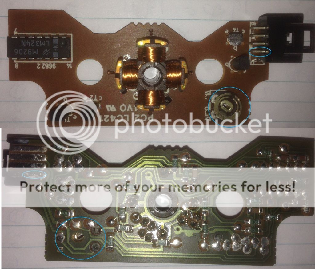
Further inspection revealed that for some reasons someone tried to scratched out two electrical traces. One of the traces leads to the 220uf caps the other leads to the lid switch-connector and the red wire that goes to the collector of transistor 8c338. Right now I have reconnected the traces with solder wires (temp fix) and fired it up. The speed is the same but this time the laser goes all the way out to the edge and stays there and no focus whatsoever. To put insults to injuries I think I smelled that beautiful electrical fume coming out from one of those 220uf caps
I'm not sure what I should do next..any help is greatly appreciated.
Aaron
Edit: The schematic show where the traces are cut and the positions of the 220uf caps.
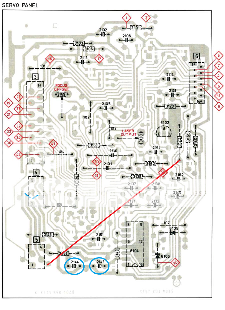
Last edited:
Welcome to diyAudio Aaron
I've no magic fixes I'm afraid. Firstly, cut print like that is commonly seen as part of manufacturer modifications... not saying that is what has happened here... but worth bearing in mind. So that could be original.
The disc spinning at speed suggests a missing rail or a missing clock signal.
Your best bet is to identify which Philips player this is based on (because that board looks very Philips to me) and then try and identify all the rails that need to be present and work from there.
Hi Mooly thank you for the warm welcome.
You are right this is based on the Phillips CDM4/27 and definitely right about the cut being manufacturer mod. Google also confirmed this.
This servo uses the following three ICs:
a. TCA0372dp2 Dual Op-Amp - driving the Laser Focus?
b. TDA8809t Radial Error Processor - signal processor for motor?
c. TDA8808t Photo-Diode Processor - signal processor for laser control?
Would it be correct to say the 8809 is not receiving the clock signal or itself-is-fried?
Aaron
I wouldn't condemn any chips just yet. Shorting that print out (and smelling burning) may well have caused further problems I'm afraid.
Firstly you need to check all the supplies are correct. Philips love using fusible resistors and the overload just created may well have caused one to either fail or go high in value. So that has to be the first step. If you haven't a full manual for the Naim then you will have to drag up the data sheets for all the chips and locate the power supply points and confirm them that way.
Secondly, the most common issue on the Philips radial pickups is failure of the 33uF caps (if it is that model and type) on the servo board under the pickup. The 33uF's are favourite but on something this age any of the small axial electrolytics that Philips use will be suspect.
I have replaced all the electrolytic caps and I found one open 1ohm (probably fusible resistor) so I took it out and bridged the connection with a piece of wire of roughly 1ohm and sure enough it is back to how it was when I first turn it on. So I guess I'm back to square one.
I will need to grab a correct resistor tomorrow, will a 1ohm 5% .25W suffice as replacement?
I will need to grab a correct resistor tomorrow, will a 1ohm 5% .25W suffice as replacement?
The standard resistor should be OK for now. Safety (fusible) resistors don't smoke and burn when overloaded in the way that a standard carbon or metal film will.
If you haven't already done so then you still need to check all the supplies are correct. Beyond that you need to concentrate on the observed fault. If the platter motor is spinning then look at the drive amplifier, its supplies and then any inputs to the chip. You then work back from there seeing if there is any obvious reason for the platter drive chip to be receiving a 'spin' voltage.
If you haven't already done so then you still need to check all the supplies are correct. Beyond that you need to concentrate on the observed fault. If the platter motor is spinning then look at the drive amplifier, its supplies and then any inputs to the chip. You then work back from there seeing if there is any obvious reason for the platter drive chip to be receiving a 'spin' voltage.
Bit of an update:
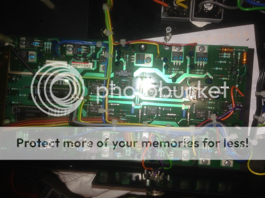
I checked the voltages on the servo and they checked out alright. Since then I have moved to the main board because with or without the servo board connected the motor still spins upon turn on and the motor cable is connected directly to the main board. I didn't wanna touch the main board before because Naim made it difficult to disassemble the board from the chassis.
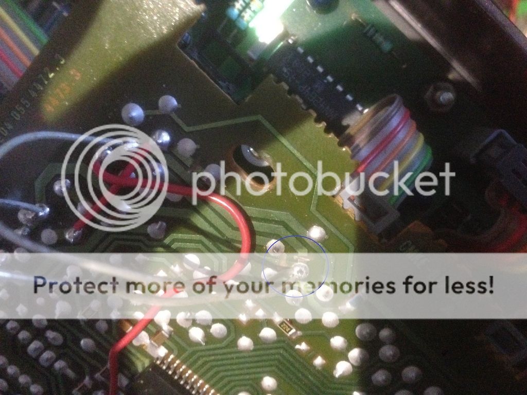
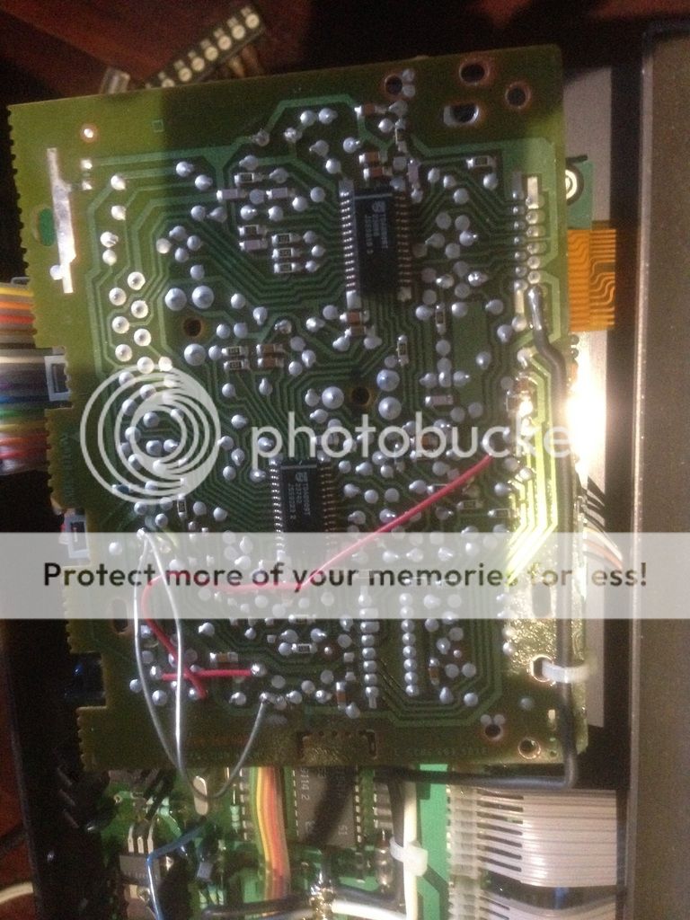
I measured 4.9V at VDD of the 7220 IC and the regulator supplying the 5V is also giving 4.9V so thats all good. Pin 9 clock out put from 7220 IC is giving 1.7V so thats good too. Now I have traced pin 9 to 7310 IC and have continuity at pin 26 of 7310 (as pictured). I dont have the schematic for the main board so it is a bit difficult to trace especially when the trace runs underneath another component and disappeared into oblivion.
Reflowed solder at the crystal oscillator and the two caps made no difference...
Aaron

I checked the voltages on the servo and they checked out alright. Since then I have moved to the main board because with or without the servo board connected the motor still spins upon turn on and the motor cable is connected directly to the main board. I didn't wanna touch the main board before because Naim made it difficult to disassemble the board from the chassis.
I measured 4.9V at VDD of the 7220 IC and the regulator supplying the 5V is also giving 4.9V so thats all good. Pin 9 clock out put from 7220 IC is giving 1.7V so thats good too. Now I have traced pin 9 to 7310 IC and have continuity at pin 26 of 7310 (as pictured). I dont have the schematic for the main board so it is a bit difficult to trace especially when the trace runs underneath another component and disappeared into oblivion.
Reflowed solder at the crystal oscillator and the two caps made no difference...
Aaron
You are really going to need the correct circuit diagrams I suspect. You have to work with what you can see and observe as being faulty... which is the motor spinning.
If you locate the motor drive amp and can confirm that it is either spinning in response to an input voltage or spinning when no input voltage is present then that is a start.
I think this is going to be an uphill struggle tbh, but you have nothing to lose in seeing what might turn up.
If you locate the motor drive amp and can confirm that it is either spinning in response to an input voltage or spinning when no input voltage is present then that is a start.
I think this is going to be an uphill struggle tbh, but you have nothing to lose in seeing what might turn up.
There's a motor board attaches to the motor. The motor board has four wires to it. Vc, Grnd, -8V, 8V printed on the board, I've measured:
Vc : 4V
Grnd : -
-8V : -10V
8V : 10V
I think the Vc is a Voltage Control that tells the IC (LM324N) on the motor board whether to speed up or slow down the motor since the voltage is at constant 4V and the speed of the motor is constant.
I took the Vc pin off and now the motor is not spinning, could this be the voltage that tells how fast the motor should spin? Mayve we work backward from here and see what is giving the 4V signal?
I might have something.
The connector to the motor board has Vc connected to the NE5532N (as pictured). The NE5532N has 2 outputs from pin1 (1out) and pin7 (2out).
This is the measurements of the pins with power on:
1 (1out): -4.3V
2 (1in-): -
3 (1in+): -
4 (Vcc-): -10V
5 (2in+): -
6 (2in-): -
7 (2out): 4.3V
8 (Vcc+): 10V
So pin 1&7 has constant power out. The power out from pin 1 (-4.3V) got cancelled to 0V by the pin7 (4.3V) at resistors in blue stripes. The 4.3V from pin7 of course went on to the motor board via Vc pin.
I thought the laser has to focus first and if there's a disc present then the spin signal will be sent to the IC but this IC seems to putout constant +- 4.3V no matter what. Is the NE5523N is fried or is there something more sinister at play?
Aaron
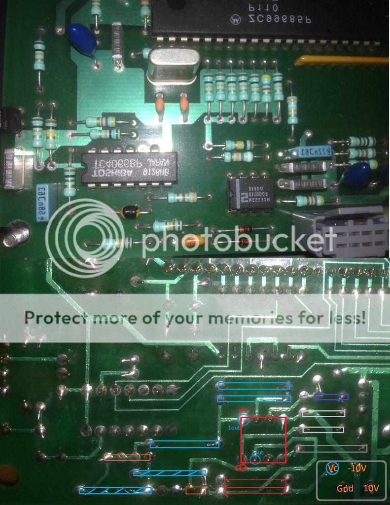
Yes, VC will be the control voltage.
It would be unusual for an opamp (the 5532) to fail, and the voltage readings seem logical in that neither output is stuck at a rail voltage. It looks like one opamp is used in inverting mode switching either a +4.3 to -4.3 or vice versa.
So I guess either pin 1 or pin 7 feeds the motor drive amp. Whichever it is, the other side of the opamp will be receiving the drive voltage from the system control but depending how the opamp is configured you may well not see a meaningful voltage on either input of the opamp.
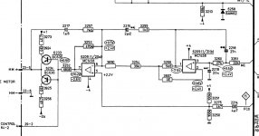
This isn't the right circuit but the idea is the same. Pin 7 would be your VC line and the input is the MC line at the right.
It might give you a clue where to look next. The opamps in yours and in the diagram could be reversed of course.
Remember this is only an outline of a typical circuit. You would need to identify the input and see if the motor responded to a change in voltage at that point.
It might give you a clue where to look next. The opamps in yours and in the diagram could be reversed of course.
Remember this is only an outline of a typical circuit. You would need to identify the input and see if the motor responded to a change in voltage at that point.
Attachments
I'm thinking its more likely the Syscon is telling the motor to spin rather than a faulty opamp.
Opamps behave predictably but its essential to have the circuit diagram to refer to and so see what is to be expected. The two inputs per opamp should normally have the same DC voltage present (whatever that may be in the application).
Opamps behave predictably but its essential to have the circuit diagram to refer to and so see what is to be expected. The two inputs per opamp should normally have the same DC voltage present (whatever that may be in the application).
On an earlier Philips CD-304MKII (SAA7210 Decoder / SAA7220 Oversampling Filter) i made the observation that unplugging the Display Board from the servo board (and by this, also diconnecting one of two controller ICs) made the disc motor spin. Maybe some communication line with the conroller is missing as well?
All the best,
Salar
All the best,
Salar
Guido, Pin 9 of the 7220 gives about 1.7V so I guess it ok?
Salar, both 7220 and 7310 is on the main board in mine.
I've isolated the NE5532 op amp from any inputs except for the Vcc+ and Vcc- but the problem still persist. I've even replaced the NE5532 and the LM324 four the transistors (although the old one tested ok) on the motor board but still no cigar.
What do you guys think? The problem lies with the motor board? or the main board?
- Status
- This old topic is closed. If you want to reopen this topic, contact a moderator using the "Report Post" button.
- Home
- Source & Line
- Digital Source
- Naim CDi servo board problem