You mentioned that with the VC line to the motor disconnected the motor doesn't spin. That suggests the motor board is OK and responds to an applied control voltage. You could rig up a 10 k preset (not critical, 10k, 47k, 100k, all are OK) across the rails of the motor PCB and then feed the wiper via a 10k into 'VC'. Altering the preset should alter the motor speed. I think its all working though.
I'm not quite sure what you done with the 5532 but you can not disconnect the actual input pins (to isolate them) because that will just cause the opamp output to swing to one or other of the rails. It would do that because it then runs 'open loop' with no local feedback wrapped around it.
I'm not quite sure what you done with the 5532 but you can not disconnect the actual input pins (to isolate them) because that will just cause the opamp output to swing to one or other of the rails. It would do that because it then runs 'open loop' with no local feedback wrapped around it.
You mentioned that with the VC line to the motor disconnected the motor doesn't spin. That suggests the motor board is OK and responds to an applied control voltage. You could rig up a 10 k preset (not critical, 10k, 47k, 100k, all are OK) across the rails of the motor PCB and then feed the wiper via a 10k into 'VC'. Altering the preset should alter the motor speed. I think its all working though.
I'm not quite sure what you done with the 5532 but you can not disconnect the actual input pins (to isolate them) because that will just cause the opamp output to swing to one or other of the rails. It would do that because it then runs 'open loop' with no local feedback wrapped around it.
Mooly I'm pretty sure adjusting the control voltage will change the speed. I isolated the 5532 not by disconnecting the feedback loops but the connection to the inputs (resistors).
Maybe the 7220 is not generating the clock signal? Can we test it without the scope? At the moment pin9 XSYS is giving out 1.7V
A scope is essential kit really, especially for work like this. There is no realistic way to look at clock signals without I'm afraid. With something like this I would start going around every pin on the relevant IC's and make sure that what would be expected is actually there. The scope excels at that because you use it juts live a voltmeter, except now you can see any problems/noise and so on as well as missing signals.
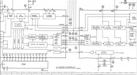
On the Philips diagram I am looking at pin 9 goes only to the RF decoder chip. If your is different then this is another reason why its vital to have the correct diagram for your player.
I tried but I couldn't find any info on the CDi schematic. I am more than happy to pay for it if anyone knows where to get one.
Looking at the ma inboard layout pin 9 goes straight to pin 26 (xtal) of the 7310. Since there are continuity to other pins (player on or off) I think that my 7220 circuitry is shorted. I'll order a replacement and see how that goes.
If there is direct continuity between pins then that needs investigating although checking in circuit is problematic.
If the pins you suspect all carry different voltages when its powered up then they can not be shorted internally... might be a quick way of proving... although it doesn't mean the chip is not faulty of course.
If the pins you suspect all carry different voltages when its powered up then they can not be shorted internally... might be a quick way of proving... although it doesn't mean the chip is not faulty of course.
I have exact this modell for remove a special issue. Unfortunately I haven't the genuine service-manual from Naim Audio or at least a schematic diagram.
Who can upload this?
This compact disc player works fine in all respects, as long I don't press the button "NEXT".
If I do this, the laser beam loss the track and don't find it again.
Now I must switch-off and switch-on again.
After do this the TOC is reading and after press the button "PLAY" the compact disc rotates and plays until the end.
This issue was already present from beginning (after purchase in brand new condition)
Unfortunately, the owner did not complain at his former hifi shop, since he assumed that the reason came from the compact discs itself.
I have replace several caps (the usual suspects) and re-solder several areas on the pcb's without any changes in the behaviour.
Therefore I think, the MCU is the reason.
I have find a Rotel-Player in working condition with the same MCU, unfortunately I haven't yet been able to invest the time for replace.
The thread therefore is here
Naim Audio CDI CD-I CD1 CD-1 CDS - only impaired Skip > Operation
An original schematic from Naim Audio would be helpful
Last edited:
Standard fault-finding applies ")
Its a long time for me (this thread) but you had a servo fault initially, and now you have it up and running by replacing the SAA7310 but now no sound.
I would work back from the analogue stages seeing what is present and what is not. Go around the audio processing chips with the scope and look for anomalies.
Re-flowed the 7310 and still no sound.
Occasionally it spills out a cracking/pop noise but otherwise dead quiet.
This is unlikely but I'm thinking I might have received a bad 7310, I bought it on eBay after all. I do however, have another one on the way.
Muting circuit might be activated? But all my regulators seem to be ok, how about a dead relay?
Mooly my scope gave up on me a few months ago and looks like I wont have access to one anytime soon.
Analogue muting issues are usually easy to prove just by looking whether any relay (or transistors) are being actively driven.
If there is doubt then just connect a speaker (via a 220 ohm) to one of the analogue output opamp output pins. It will drive a speaker like that and confirm whether audio is present.
If there is doubt then just connect a speaker (via a 220 ohm) to one of the analogue output opamp output pins. It will drive a speaker like that and confirm whether audio is present.
Using the input I connect to different outputs at various amp stages all the way back to the output from the TDA1541A, got nothing. I measured the output pins (L&R) and sees ~2.2 volts so its ok in the mean time.
I used my iphone output and connect it to the inputs at various amp stages all the way back to the TDA1541A and I got sounds coming out from the output. So the opamp sections is ok.
Now I need to know whether the 7310/7220 or the TDA1541 is not "working". Any ideas on how I can test for the digital audio before the TDA?
Cheers
You would really need a scope and then its a case of going around every pin and seeing that nothing odd shows up. You can't check data lines as such but you can see if there is activity present and whether the logic levels are correct. Activity usually means a given line would be OK. If you have access to another player with a similar chipset then comparing DC voltages on all pins might just show something.
Faults like this are not easy though
Faults like this are not easy though
So I did a few more tests to isolate the problem. I got the eye pattern at the HF point so the laser is OK albeit not very clear. This line then goes to the decoder 7310 (pin 32) and out at pin 2. The waveform at pin 2 is not what expected, this waveform is the same as measured at the output posts.
Im I right in thinking either the 7310 or the 7220 is toasted? I'm leaning toward the 7310 because it is the decoder and the waveform measured at pin2 doesnt look like it is as it should. Ive already ordered another 7310 and a saa7220 so we will see which one is the culprit.
Any advice and suggestions are greatly appreciated.
HF point

Output pin 2 of 7310

Output posts

Im I right in thinking either the 7310 or the 7220 is toasted? I'm leaning toward the 7310 because it is the decoder and the waveform measured at pin2 doesnt look like it is as it should. Ive already ordered another 7310 and a saa7220 so we will see which one is the culprit.
Any advice and suggestions are greatly appreciated.
HF point
Output pin 2 of 7310
Output posts

- Status
- This old topic is closed. If you want to reopen this topic, contact a moderator using the "Report Post" button.
- Home
- Source & Line
- Digital Source
- Naim CDi servo board problem