They found out how it works the firmware to appropriate control all the process. There is a small software loaded into the mentioned applications (boards), which it fix the well functioning. All these are not to be seen from outside, and I doubt all these who "did it" are willing to speak out about...
I did the same, tapping I2S lines at the input of an PCM1794, and it worked very nice (for stereo). It is not the same for 203 digital audio system, and it is more complicated for multi-channel setup...
I did the same, tapping I2S lines at the input of an PCM1794, and it worked very nice (for stereo). It is not the same for 203 digital audio system, and it is more complicated for multi-channel setup...
Last edited:
Coris,
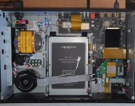
I have listen to new out of box Oppo 205
sound was bad - dull soft not detailed
what are critical mods to fix that, do you have deffinite to do mods
replace I/V and differential output opamps to OPA1612 ?
Yes, I had similar impressions as well.
The main issue of this device is the power system, for both digital and analogue sections. First of all, one should replace the original SMPS for digital section, with an LPS. This is the first step and most important to lift up the overall quality of the outputted signals, for both sound and picture. Then the analogue power system it need to be corrected quite much to improve the sound. The third step is improving the clock system of the device, which it add more quality improvement. Last step is eventually replacing of the components/opamps in post DAC signal processing stage. Even with the original components in analogue stage (after DAC), the player it sound quite good, with the rest of the upgrades in place.
These are the main directions, but the full upgrade in detail is a quite laborious work...
Hi, first post on this forum.
With the lock-down boring me so much I have decided to modify my OPPO UDP-203 player and Onkyo RZ900 AV amp.
Interestingly both the OPPO and Onkyo use the AK4458 DAC, so comparing the two post-modification will be interesting. Currently the OPPO sounds very slightly clearer in the highs through the analogue outs to the RZ900 than when using the OPPO HDMI outs to the Onkyo. Speakers are B&W 702 with the bi-amp feature of the Onkyo to drive the Bass and Mid/High drivers separately.
I have taken the trouble to read this thread and thanks to all the contributors for bringing me up to speed on the UDP-203.
My plan for the UDP-203 upgrade will follow the core advise in this thread. I’m an experienced electronics tech and past modder (been quite for the last 5 years).
One limitation I have is that the RZ900 does not have multi-channel analog inputs, so my plan is to use the OPPO L/R analog outputs for stereo music and the OPPO HDMI outputs for multi-channel music and movies. I guess the post mod listening tests will really decide this, at the moment I just feel that avoiding the HDMI link between the OPPO and Onkyo would be the best approach.
Planned OPPO UDP-203 mods are:
1. LPS, having read this thread it’s a no-brainer to use the Coris LPS if I can find where to purchase one (Hello Coris 😊).
2. Replace the L/R Op Amps (stock NE5532) to OPA1634 (I have some on hand from my last project).
3. Replace the AC coupling capacitors with Nichicon “Fine Gold” audio grade electros bypassed by 1uf polypropylene.
4. Look at the analog board power supply filter capacitors based on the advice from this thread.
5. Consider the HDMI Clock on the digital board to improve the HDMI jitter, I will need some advice on that mod as to what the best approach is.
The plans for the Onkyo RZ900 are the same, OpAmps to OPA1634 and coupling capacitors to “Fine Gold” and polypropylene bypass.
I have the Service Manual for the RZ900 so can see the circuit design and areas I need to target. I have not been able to find the Service Manual for the OPP UDP-203 which is a pain.
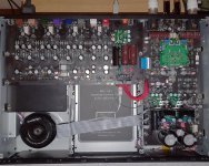
I read with interest the post by Coris on 11 Jan 2020 concerning the DAC Board 203. I had found it interesting that there are AC coupling caps between the AK4458 DAC and the OpAmp stage, this is interesting because the RZ900 also uses the AK4458 DAC but it does not use AC coupling caps (see image of the RZ900 DAC and OpAmp stage below).
I have a reasonable measurement system so I intend to make before and after measurements of the noise floor and distortion spectrum and will post the results.
Thanks for the good read.
With the lock-down boring me so much I have decided to modify my OPPO UDP-203 player and Onkyo RZ900 AV amp.
Interestingly both the OPPO and Onkyo use the AK4458 DAC, so comparing the two post-modification will be interesting. Currently the OPPO sounds very slightly clearer in the highs through the analogue outs to the RZ900 than when using the OPPO HDMI outs to the Onkyo. Speakers are B&W 702 with the bi-amp feature of the Onkyo to drive the Bass and Mid/High drivers separately.
I have taken the trouble to read this thread and thanks to all the contributors for bringing me up to speed on the UDP-203.
My plan for the UDP-203 upgrade will follow the core advise in this thread. I’m an experienced electronics tech and past modder (been quite for the last 5 years).
One limitation I have is that the RZ900 does not have multi-channel analog inputs, so my plan is to use the OPPO L/R analog outputs for stereo music and the OPPO HDMI outputs for multi-channel music and movies. I guess the post mod listening tests will really decide this, at the moment I just feel that avoiding the HDMI link between the OPPO and Onkyo would be the best approach.
Planned OPPO UDP-203 mods are:
1. LPS, having read this thread it’s a no-brainer to use the Coris LPS if I can find where to purchase one (Hello Coris 😊).
2. Replace the L/R Op Amps (stock NE5532) to OPA1634 (I have some on hand from my last project).
3. Replace the AC coupling capacitors with Nichicon “Fine Gold” audio grade electros bypassed by 1uf polypropylene.
4. Look at the analog board power supply filter capacitors based on the advice from this thread.
5. Consider the HDMI Clock on the digital board to improve the HDMI jitter, I will need some advice on that mod as to what the best approach is.
The plans for the Onkyo RZ900 are the same, OpAmps to OPA1634 and coupling capacitors to “Fine Gold” and polypropylene bypass.
I have the Service Manual for the RZ900 so can see the circuit design and areas I need to target. I have not been able to find the Service Manual for the OPP UDP-203 which is a pain.
I read with interest the post by Coris on 11 Jan 2020 concerning the DAC Board 203. I had found it interesting that there are AC coupling caps between the AK4458 DAC and the OpAmp stage, this is interesting because the RZ900 also uses the AK4458 DAC but it does not use AC coupling caps (see image of the RZ900 DAC and OpAmp stage below).
I have a reasonable measurement system so I intend to make before and after measurements of the noise floor and distortion spectrum and will post the results.
Thanks for the good read.
Attachments
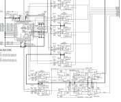
When about post DAC opamp stage in these two devices (Oppo 203 and RZ900), please note that are some design differences. Oppo have chosen a more simple way to treat the 2,5v DC offset at the AKM chip outputs, by using AC coupling caps. RZ900 it use another way. Also another (better) way is using a fully balanced opamp connected directly to the DAC output. I use this solution for my balanced (XLR) stereo added module.
As the original Oppo design of 203 audio board is, the AC coupling in between DAC outputs and the further opamp stage, is necessary. There is no any service manual or schematics for any Oppo devices available out there...
OPA1612 it may be a good choice for replacing the original opamps on 203 audio board. Easy and good results... Well, the rest of the improvements on board may be necessary as well, for an overall audio quality lifting.
Also please note that the use of transistors mute circuits on audio 203 board, it make necessary the use of a second AC coupling stage at the opamps outputs. I appreciate this double AC coupling approach as unfortunate...
Else, finding out how getting an LPS for 203 it may not be that difficult... (PM).
Last edited:
Hi peeps
I recently installed a HDMI/I2S card from Oppomod in my Oppo 203. Unfotunately, there's a weird glitch as the native DSD output is out of phase. It's fine/in phase when converted to PCM. I have thoroughly checked with a set up disc and it confirms that the DSD signal is definitely out of phase. If the + and - speaker cables are swapped, it's then in phase.
Has anyone come across this at all? I have emailed Jaehong and he has asked that I post on forums to see if others have come across this. He could be thinking that it's all in my head of course, .
.
The best example to describe the out of phase situation would be that in a song the singer's position can't be located to a single point.
I would very much appreciate it if others with this oppomod are able to test and provide feedback on hear as I am rather dumbfounded.
Thanks
Van
I recently installed a HDMI/I2S card from Oppomod in my Oppo 203. Unfotunately, there's a weird glitch as the native DSD output is out of phase. It's fine/in phase when converted to PCM. I have thoroughly checked with a set up disc and it confirms that the DSD signal is definitely out of phase. If the + and - speaker cables are swapped, it's then in phase.
Has anyone come across this at all? I have emailed Jaehong and he has asked that I post on forums to see if others have come across this. He could be thinking that it's all in my head of course,
.The best example to describe the out of phase situation would be that in a song the singer's position can't be located to a single point.
I would very much appreciate it if others with this oppomod are able to test and provide feedback on hear as I am rather dumbfounded.
Thanks
Van
I just managed to find the solution to my DSD phasing issue. It turns out that my oppomod HDMI/I2S pinout configuration doesn't use the PSAudio standard. On my Terminator DAC, the config LED needed to be set to 1x=0, 2x=0 and 4x=0 instead of the PSAdio of 1x=1, 2x=0 and 4x=0. It was pure luck I managed to sort this and it has been a great relief. Thanks for reading.
Please tell me the pinout of connector CN1 on the DAC board (OPPO 203)? The idea is to take signals SCLK, SDATA, LRCLK, MCLK from there and feed them to the I2S to SPDIF convertor and as a result receive a stereo signal SPDIF TTL for further supply to an external SPDIF reclocker. It is not particularly clear whether there is a MCLK signal on
CN1 connector, or can it be taken somewhere else?
CN1 connector, or can it be taken somewhere else?
Please tell me the pinout of connector CN1 on the DAC board (OPPO 203)? The idea is to take signals SCLK, SDATA, LRCLK, MCLK from there and feed them to the I2S to SPDIF convertor and as a result receive a stereo signal SPDIF TTL for further supply to an external SPDIF reclocker. It is not particularly clear whether there is a MCLK signal on
CN1 connector, or can it be taken somewhere else?
I think such information is not easy at all to get it, except your own investigations on the CN1 pinout. The amount of work/time to identify the signals on that interface is so high, that you will not be then very happy to share it, if you eventually will identify the signals...
I do not have either such information, and yet not proceeded to the work to get it...
In my opinion it may be there also about some particularly/proprietary signal configuration, in order to properly configurate the digital interface accordingly to the firmware design. Supposing one my identify the standard I2S signals, then these it have to be processed/synchronised accordingly to the device software, for that signals being usable further. Such it could be quite difficult indeed.
Last edited:
I'd be interested to hear how a fully modded 205 compares to a fully modded Panasonic 9000, I definitely preferred a stock 9000 to a stock 205, I had both and A-B'd for several weeks
I have the same assumption about better picture on stock UB9000, than stock 205...
Hi Coris,
You mentioned earlier splitting the +12v rail between opamps and avcc and adding a pre reg for the avcc (adm7151) regs. Where did you make this split? I noticed all the +12v is connected across the pcb so for opamps and the rest but cannot find a direct route to the avcc regs.. Perhaps you remember how you did this?
Thanks, Sander
Hi Sander,
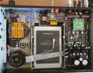
Indeed, the +12v rail it goes all the ways on stereo board. These traces it are mostly placed on the inside layers of the board (not visible). Measurements should be made to identify where the +12v it may come into the targeted circuits/regulators. The preregulator it is meant to be placed after the rectifier bridge on the power rails (7v) for the DAC regulators. If the multi-channel board is not used, then the available power line (7v) it can be used, with an preregulator, to power the AVCC regulators for stereo section.
The DACs AVCC regulators (ADM7151) it are originally powered from 12v.
Update on my power supply mods and getting the player to run much cooler(!):
- main caps changed to 33000uf with 0,1uf bypass
- new toroidal transformer with more power per rail, 2x6vAC + 1x10-0-10vAC (instead of 15v)
- removed original rectifier bridges, replaced with schottky
- power check on startup is pretty basic and not related to rail voltages, just needs to see voltage on all three rails
- now running the 7v rails @ 5.5v (lower than 5v doesn't work) about 10 degrees cooler on all regs in this rail and much more within spec of all the different regs, 7v is too high for optimal thermal and noise performance
- also added preregs for both 5.5v rails (ti tps)
- same for +/- 12v, original power supply was approx 18v raw before regulation. changed standard regs for ti tps low dropout / low noise regs. by changing the transormer to lower voltage / higher amps we get 13v raw before the regs. now they run cold instead of hot!
I was amazed at the bad solder quality of the rectifiers! They just came off when i tried to grab them with a ceramic tweezer!! Tip for every owner: reflow these joints!
Will post some pics soon when all is ready!
- Home
- Source & Line
- Digital Source
- Oppo new UDP series players - 203/205 - Discussions, upgrades, modifications