Well, the figures in its self are not unusual high. The Vf is almost the same for standard diodes/bridges. So, then it come the question: why replacing the original bridges? What it may be the differences in between the original rectifier bridges, and the Schottky replacement? The speed of the Schottky is not important here, as the frequency to be rectified is very low...
Last edited:
...In the 205 they are now using 3 bridges (Vishay DF02S). Is there anybody who changed these bridges for a Schottky bridge? Could the PanJit TS2100S be an altenative? If this is possible, I think this is a more elegant solution than a construction with 4 diodes.
Hi Roborgje
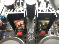
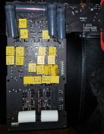
I replaced the DF02S with the Digikey Part# CBRSDSH2-40TR13-CT-ND
This bridge specs are:
Vf= 450mV @ 2A. Vr=40V reverse voltage. >200mA (Io). Fast Recovery =< 500ns, Leakage typical 40µA @ 40V. US$1.25. It would be hard to do better than these specs.
The 2nd reason is that this bridge is about the same size as the DF02S and soldering is easy.
Result is a quieter noise floor.
Also advisable to add bypass caps to the reservoir caps Elna 6800uF and 3300uF. My preferred bypass is the Cornell Dublier 940C .01uF. Film. 500VAC 3000VDC or the Vishay MKP-1837 0.01uF 100Vac-160Vdc based on humblehomemadehifi's extensive capacitor tests. WIMA MKP10 is also good but maybe not as good. Avoid WIMA MKS4. Some folks prefer 1uF or 0.1uF, but my ears cannot tell the difference.
However, to me, the biggest bang for the buck is replacing the +/-12V stock regulators with ultralow noise, high PSRR TPS7A4701 and TPS7A3301. You can get the pair finished on PCB from eBay etc for around $20 to $35 total. I mount them on the existing heat sinks after setting the voltage separately first with a 100-200 ohm load.
The improvement from the regulators is significantly larger than the schottkys and filter caps and quite easy to do. Sonics improvement is like moving quite a few rows closer to the performers.
Another wonderful improvement is the Coris LPM. I just marvel at the excellent design and engineering of this very high quality board. Has pretty well every great feature you can think of. I think Coris has improved his LPM nicely since the Oppo 105. (I also have the 105).
With these mods, you have a giant leap in performance added to a machine with unmatched features. Sonics are organic and analogue like, without digital haze. For the first time, I have a digital front end which rivals my excellent analogue LP setup.
Denis
Hi Denis,
when I changed the diodes in my BDP105 to UB860 is was quite a improvement. So I think I will change the bridge in the UDP205 in 4 MUR120 diodes. The 860's are a bit too big (and 8A).
I hope I don't have to remove the stereo board for this rather small "operation."Saves a lot of work.
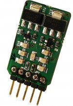
I do not now if I dare to make the mod with the +-12V supply you supposed because I do not quite understand the mod. Does 1 board replaces the 2 regulators? If that is the case, how did you connect it then? (Picture ??)
Is this module also getting so hot?
P.S.: Coris' LPS is the next big thing of course.
P.S.II (not belonging in this thread): I saw you mentioned the C-test in HumbleHomemadehifi. I tried the Duelund Silver bypass. Worth trying!
Rob
when I changed the diodes in my BDP105 to UB860 is was quite a improvement. So I think I will change the bridge in the UDP205 in 4 MUR120 diodes. The 860's are a bit too big (and 8A).
I hope I don't have to remove the stereo board for this rather small "operation."Saves a lot of work.
I do not now if I dare to make the mod with the +-12V supply you supposed because I do not quite understand the mod. Does 1 board replaces the 2 regulators? If that is the case, how did you connect it then? (Picture ??)
Is this module also getting so hot?
P.S.: Coris' LPS is the next big thing of course.
P.S.II (not belonging in this thread): I saw you mentioned the C-test in HumbleHomemadehifi. I tried the Duelund Silver bypass. Worth trying!
Rob
TPS7A regulators for +/-12V rails
Hey Roborgje
No you replace each regulator separately - TPS7A7401 for positive and TPS7A3301 for negative. I'll send you email of detail instructions for the TPS7A regulators.
Yes I used the Duelund tinned copper bypass caps for the supertweeter of my Maggie 1.7 speaker crossover mod. Outstanding, but a bit too expensive as a bypass for electronics and would not have as big a bang for the buck.
Attachments
Hi Denis,
So I think I will change the bridge in the UDP205 in 4 MUR120 diodes.
Rob
If you go with 4 discrete diodes, you'll need to make a mini board for each bridge and the work and soldering will be quite extensive. Why not use a schottky bridge like I suggest. Cannot be simpler and I bet you will not be able to hear any difference.
But if you are inclined to make your own bridge, then I would also suggest adding a snubber to each to eliminate transformer ringing oscillation.
Denis
Hey Roborgje
No you replace each regulator separately - TPS7A7401 for positive and TPS7A3301 for negative. I'll send you email of detail instructions for the TPS7A regulators.
Hello from Italy, I would be interested in making this change on my OPPO Sonica Dac, which has the same power supply (so it seems to me), you could send an email with explanations also to me for courtesy.
Thank you very much
Gigi

Good evening Coris,Best of all in this field is to just bypass the AC coupling caps with a wire, and use the outputs in DC coupling. As usual it should be there an few mV DC offset, which it should be tolerated by most amp/preamps. At least this is the easiest and cheapest solution. If your preamp/amp it may have coupling caps on its inputs (as most do), then is no reason having a redundant AC coupling into the signal path. A measurement of the DC offset, it should be necessary to confirm the low offset. Measure the DC level before the existing 100µ caps.
If AC coupling should be chosen, then any bigger capacity non polarised caps it should be better than the original ones (bypassed with film caps, of course).
Accordingly by the book and calculation, these AC coupling caps for the frequency range of a audio signal, an 10µ value, or so it should be enough. In fact, as bigger the coupling cap value, as better the sound quality in the low end of the spectre. This is hearable. Not all the time the results of (by the book) calculations it fit with the human perception...
Tuttavia, nel tuo caso, se si può avere un accoppiamento DC nella vostra catena, quindi è la soluzione migliore (senza tappi). [/CITAZIONE]
However, in your case, if you can have a DC coupling in your chain, then is the best solution (without any caps).
I enclose the diagram of the input stages of my McIntosh MC601, you can confirm that the capacitor present from 10uF, I would protect from DC components output from the modified sound card by removing the 100uF (I own an OPPO Sonic DAC that uses the same stages of 203 -205).
Thank you View attachment Input Stage.doc
Hi beeppeep61
Yes indeed, if you have that cap on your amp input, then you can safely use the Oppo UDP/Sonica on DC coupling (wire bypassing the 100µ caps on its outputs).
Yes, the post DAC stages on Sonica are similar to Oppo players.
Personally, I would like to have a film cap 0,1 - 1µ) in parallel with that 10µ cap on the McIntosh amp inputs as well...
100mA sound too low....
I think a more straightforward solution for 205 is the ones by Sparkos Labs:
Discrete Voltage Regulators - SparkoS Labs Inc.
Amazing spec. on paper - I have ordered a pair - will update....
I think a more straightforward solution for 205 is the ones by Sparkos Labs:
Discrete Voltage Regulators - SparkoS Labs Inc.
Amazing spec. on paper - I have ordered a pair - will update....
+/-12V Regulators
You are replacing LM2940/LM7912 regulators which are rated for 1A. The actual load on this rail is likely >0.5A on the +ve rail due to the relays. I would use a 1A rated regulator.
The Sparkoslab discrete regulators are nice, but expensive. Their claims of superior performance is against regular regulators, and they were probably designed quite a few years ago. There are many such discrete designs which are no longer as compelling because nowadays you can find Ultralow noise, ultra high PSRR monolithic regulators for very attractive price.
For 1A, the TPS7A4701/TPS7A3301 are amazing - with noise as low as 4uVrms and PSRR as good as 82dB. These are available finished in a TO-220 format for a direct physical replacement of the stock regulators and allow you to use the stock heatsink. If you need 0.5A or less, you would look at the LT3045 with even lower noise (0.8uVrms).
If you are not sure about getting these on eBay AMZN etc from China, you can take a look at http://www.ldovr.com which offer better quality, better design for $20.
Or if you're really ambitious, you can check out the shunt replacement regulators by famous PSU provider Paul Hynes 3 Terminal Regulator Replacements
Looking fwd to you experience.
Denis
(PS: I have no financial or any other interest in the above providers.)
100mA sound too low....
I think a more straightforward solution for 205 is the ones by Sparkos Labs:
Discrete Voltage Regulators - SparkoS Labs Inc.
Amazing spec. on paper - I have ordered a pair - will update....
You are replacing LM2940/LM7912 regulators which are rated for 1A. The actual load on this rail is likely >0.5A on the +ve rail due to the relays. I would use a 1A rated regulator.
The Sparkoslab discrete regulators are nice, but expensive. Their claims of superior performance is against regular regulators, and they were probably designed quite a few years ago. There are many such discrete designs which are no longer as compelling because nowadays you can find Ultralow noise, ultra high PSRR monolithic regulators for very attractive price.
For 1A, the TPS7A4701/TPS7A3301 are amazing - with noise as low as 4uVrms and PSRR as good as 82dB. These are available finished in a TO-220 format for a direct physical replacement of the stock regulators and allow you to use the stock heatsink. If you need 0.5A or less, you would look at the LT3045 with even lower noise (0.8uVrms).
If you are not sure about getting these on eBay AMZN etc from China, you can take a look at http://www.ldovr.com which offer better quality, better design for $20.
Or if you're really ambitious, you can check out the shunt replacement regulators by famous PSU provider Paul Hynes 3 Terminal Regulator Replacements
Looking fwd to you experience.
Denis
(PS: I have no financial or any other interest in the above providers.)
Halo,
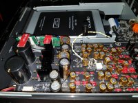
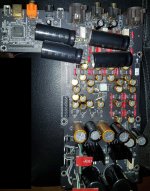
I have finished my 205 Mods. Analog board caps+resistor are all replaced (audionote kaisei and PRP resistor) + low noise dexa + scotty. I replaced blackgate output caps 100uf to 2.7uf film and it sounds more natural, no problem whatsoever even thought it is much smaller value. Then I bypass with cheap yellow $0.2 X2 0.48uf caps with low esr (100-140Mohm)
Other mods are LPM, new main clock and 100mhz analog clock, neutrik outputs, furutech NCF outlet with neotech solid copper.
It transforms vanilla 205 (sounds crap) into something special, no comparison before and after. I think I have enough.
Attachments
Has anyone actually measured the DC offset on the stereo output (before the caps) ?
Some DAC's this may be +2.5v and others the DC value is just either the difference in each DAC output or just the Op Amps input offset voltage.
Since i don't have a schematic I cant' tell.
Thanks
Todd
Some DAC's this may be +2.5v and others the DC value is just either the difference in each DAC output or just the Op Amps input offset voltage.
Since i don't have a schematic I cant' tell.
Thanks
Todd
Has anyone actually measured the DC offset on the stereo output (before the caps) ?
Some DAC's this may be +2.5v and others the DC value is just either the difference in each DAC output or just the Op Amps input offset voltage.
Since i don't have a schematic I cant' tell.
Thanks
Todd
My 205 is directly connected to a pair of Aleph 1.2 monos.
I bypassed the caps - DC offset measured in milli volts - I think it was about 10mV or so - at the time I deemed it to be insignificant.
I've been using it like this for over six months now with no issues whatsoever....
Has anyone actually measured the DC offset on the stereo output (before the caps) ?
Some DAC's this may be +2.5v and others the DC value is just either the difference in each DAC output or just the Op Amps input offset voltage.
Since i don't have a schematic I cant' tell.
Thanks
Todd
The DC offset on stereo output (as multi-channels as well) it may be under 10mV. As usual, it actually vary in between +/-5mV.
The DC offset on stereo output (as multi-channels as well) it may be under 10mV. As usual, it actually vary in between +/-5mV.
Great, less than 10mv and I can bypass the caps !
Thanks
- Home
- Source & Line
- Digital Source
- Oppo new UDP series players - 203/205 - Discussions, upgrades, modifications