The power relay signal is active in 203 model...
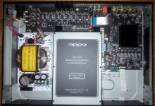
Quite happy to find out that the relay circuit on the main board of 203 model is active, even thought this is not used. It seems that Oppo chosen to produce the main board for both models 203 and 205 identical and fully populated. This is quite good!
It is about the relay which it have to power on/off the toroid for analogue stage in 205 model. This function does not exist for 203.. In 203 the relay and some other components necessary to realise this function are not populated on the SMPS board, but the signal which it should activate this relay it is active, and it output from the main board.
This is really very fortunate for further modifications/improvements.
Some users of 203 model may want to improve the clock system, by adding some dedicated and better clock approaches or clock boards. The power for these boards it can be now controlled by this relay signal output, already active on main board.
I already adapted my LPM to use this signal for 203 model improvements too.
This LPM is designed to fit into both 203 and 205 models. So the power relay circuit is already on board and it can be populated and used for 203 model too, to control a supplementary PSU for a clock board.
I use also this relay signal to control my battery powered clock board in a more convenient manner (no any modification necessary on the main board).
I decided to provide the LPM from now on, ready for the use of my clock board as an eventual future improvement, which is much more easy now to be installed by the user himself (only coaxes are needed to be soldered in place).
Now my clock board is implemented into a 203 model, and the results are already very impressive. Especially for picture quality. Quite dramatic improvement in reproducing the colours level into the picture, increasing of the tonal richness as the very fine details.
The USB interface quality is also improved as a consequence of this improved clock system, and the sound quality is also lifted up and very noticeable (the audio board it is not yet modified).
My clock board for 203 model it include an high quality 25Mhz oscillator for the UHD drive decoder chip (0,28ppm temperature stability and -130dB phase noise).
Hereby is pictured the 203 clock system improvement...
Attachments
Last edited:
Well, I have to admit that AK4458VN DAC is very good. Accordingly improved the board this chip is part of, the signal outputted it can be over any expectations.
There is a different sound than from Sabre chip, but I`m very surprised by the high quality one can get out of this AKM DAC... Very good indeed!
The analogue sound stage in 203, it can perform really amazing....
There is a different sound than from Sabre chip, but I`m very surprised by the high quality one can get out of this AKM DAC... Very good indeed!
The analogue sound stage in 203, it can perform really amazing....
Well, I have to admit that AK4458VN DAC is very good... the signal outputted it can be over any expectations... a different sound than from Sabre chip, but I`m very surprised by the high quality one can get out of this AKM DAC... Very good indeed!... it can perform really amazing....
Yes, I suspected this would be a major improvement to the 203, but then others said that Oppo should have used a premium 2-channel DAC and what a shame... but Oppo was only ever going to use a single multi-channel DAC as per '93 and '105 and don't understand what Oppo thinks and does.
In fact, it would be hard to think of a better DAC that Oppo could have chosen outside the ESS stable. It is a premium 32bit multi-channel DAC.
.
Oppo have for sure their own appreciations, judgements, and at least some particular interest as company) in choosing their components for their products.
The DAC chip into this 203 model is in fact a cheap device, and it is known that the analogue out stage of a lite version of an UHD player, it may not be meant as a just high end output... This device as the rest of the Oppo products it become high end devices only after improvements (also an already known now "tradition").
The audio board in this model is also a cheap design. They chosen multi-channel approach as it may satisfy the most of the users/customers. The stereo channels into this multi-channels configuration it got a little bit more attention from designers, so to perform a "one mm" over the quality of the rest of the channels...
I was focusing my improvements also on these two stereo channels. There is no enough place on the small board to improve everything, and the number og necessary components have to ve multiplied by 7...
However, there is possible to improve the power system for DAC chip, and this it brings dramatic results.
Oppo still use transistors mute circuits for this lite version player, its analogue audio stage. This is bad for the final signal quality, even thought it allow a increased quality than the previous similar stages in 103/101 models. I replaced this mute circuit with relays (for stereo channels only).
This type DAC chip it provide on its outputs, a ready for use analogue signal. There is further added only a buffer more. Everything is AC coupled (in a cheap maner by Oppo original design)...
I would liked to experiment an adding of the DAC four differential channels outputs into a stereo set up, but I had no time for such, and more I do not own myself the device I worked on... I chosen only "safe" improvements...
However, an 203 model with a linear PSU for digital stage and the DAC board, my clock system battery powered, and the analogue audio board improved accordingly, it sound over any expectations (just amazing dynamics, fidelity, resolution, and spatial sound scene), so with this cheap AKM DAC on board.
Waiting now for next 205 model with Sabre Pro inside to be out, to make some comparatives...
Last edited:
My friend who is expert in mechanism made beautiful chassis and loading stabilizer .
You can see in my blog at Jae H. Lee Blog :: Jae H. Lee Blog
here is some photos


You can see in my blog at Jae H. Lee Blog :: Jae H. Lee Blog
here is some photos
Last edited:
Do you get a better picture and sound out of the electronic system, when you place the boards into another chassis?
Actually this is not a Oppo device, but something else, called Serenity. This thread is about improving an Oppo product/player. Please keep on topic.
Actually this is not a Oppo device, but something else, called Serenity. This thread is about improving an Oppo product/player. Please keep on topic.
Last edited:
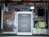
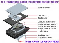
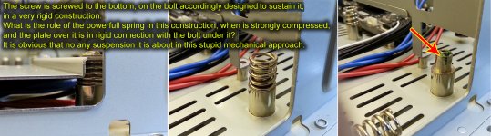
I would like to point once more on the misleading way Oppo it present the mechanical mounting of their driver in all the player models they produced/produce.
Oppo it show in their 3D design of the driver unit, the springs which it suggest about a elastic mounting of the driver into the chassis. In fact (see the pictures hereby) the mechanical mounting of the driver in Oppo all models it is done in a very rigid (and stupid) way, even thought it are used some springs.
I only wonder about the role of these quite powerful it springs used in this approach...
Hereby also my correction for this wrong mounting design...
Attachments
Last edited:
I only wonder about the role of these quite powerful it springs used in this approach...
I wonder, and I don't have a player open in front of me, if this is only so that they can align the mechanism easily so that the tray can be adjusted for ejection with obstruction?
.
You know, there is no need of any adjustment here. If all the parts are screwed in completely (to bottom, and how is actually done), everything it fit perfectly as the mechanical design, and fabrication are enough precisely.
The all four screws are screwed to the bottom and the plate which support the driver is in a very rigid and good mechanical connection with all the four bolts, and chassis. The springs are well compressed, and it press in between the bolts and the screwed in plate over it. These springs it exercise a force which is not necessary at all here, so how it is actually executed the mounting approach. Even thought the screws shouldn`t be screwed in to bottom, the very powerful springs it will exercise a so strong force in between the bolts and the plate, realising a very good and rigid construction.
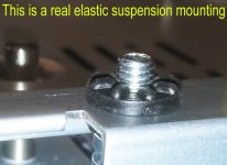
The only elastic suspension which it could be made using these springs, is to attach the plate on one end of the springs, while the another end of the spring it have to be attached to the chassis (no any mechanical connection in between the driver plate and the chassis, but only through the spring). In such case, the springs it will be in between the plate and the chassis, and the elastic suspension is realised. In such scenario, the springs should be of a much softer type. The force of the actual springs is very strong...
I have to point also here on another aspect. The plate and its mounting approach is designed, having in mind a real elastic suspension mounting. The plate and the bolts planted into the chassis, it realise a limiting, so that the driver should`"float" freely in place, but only in between some limits. For unknown reasons Oppo have chosen a such stupid rigid mechanical mounting, where the springs it have no any function, and most important, not realising any elastic suspension at all...
This mounting it is not changed, corrected or improved since 95 model (I haven`t seen yet myself the 83 model inside)... Always exactly the same mechanical approach and chassis design.
P.S. I just come now on the idea that the springs are planted there in place only as a decoration, to suggest (mislead) that it may be about a suspension approach, so how they show off in the 3D exploded design of the driver. In fact it is not about any suspension!
The all four screws are screwed to the bottom and the plate which support the driver is in a very rigid and good mechanical connection with all the four bolts, and chassis. The springs are well compressed, and it press in between the bolts and the screwed in plate over it. These springs it exercise a force which is not necessary at all here, so how it is actually executed the mounting approach. Even thought the screws shouldn`t be screwed in to bottom, the very powerful springs it will exercise a so strong force in between the bolts and the plate, realising a very good and rigid construction.
The only elastic suspension which it could be made using these springs, is to attach the plate on one end of the springs, while the another end of the spring it have to be attached to the chassis (no any mechanical connection in between the driver plate and the chassis, but only through the spring). In such case, the springs it will be in between the plate and the chassis, and the elastic suspension is realised. In such scenario, the springs should be of a much softer type. The force of the actual springs is very strong...
I have to point also here on another aspect. The plate and its mounting approach is designed, having in mind a real elastic suspension mounting. The plate and the bolts planted into the chassis, it realise a limiting, so that the driver should`"float" freely in place, but only in between some limits. For unknown reasons Oppo have chosen a such stupid rigid mechanical mounting, where the springs it have no any function, and most important, not realising any elastic suspension at all...
This mounting it is not changed, corrected or improved since 95 model (I haven`t seen yet myself the 83 model inside)... Always exactly the same mechanical approach and chassis design.
P.S. I just come now on the idea that the springs are planted there in place only as a decoration, to suggest (mislead) that it may be about a suspension approach, so how they show off in the 3D exploded design of the driver. In fact it is not about any suspension!
Last edited:
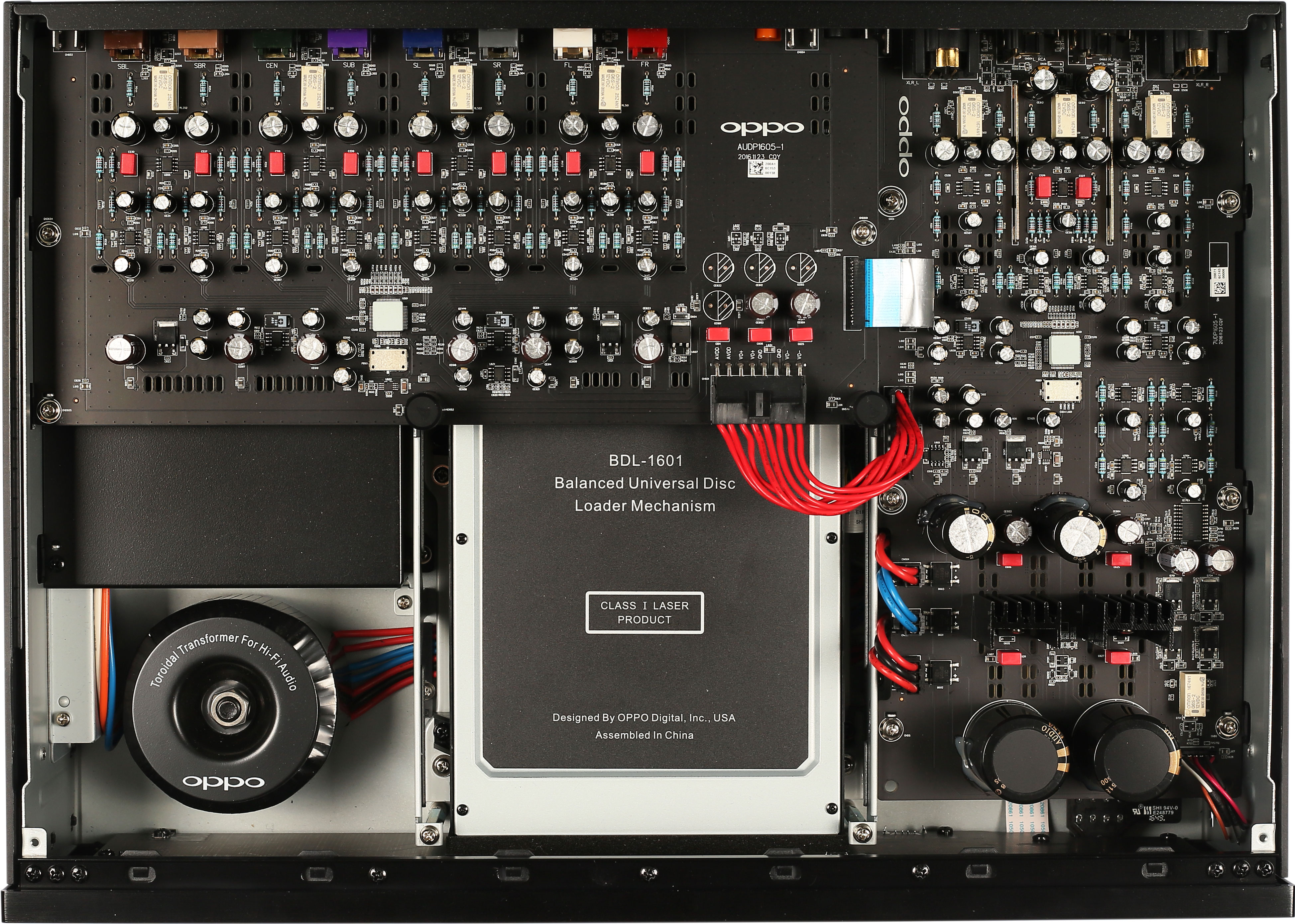
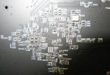
Looks like separate clocks for Stereo and Multi-channel. Rectangular with four black corner dots - that has to be the oscillators. If so, not a bad thing and gets rid of that Texas chip sending a balanced clock signal up to the M-CH via the ribbon.
Go to Oppo's website for full resolution hit "+" on the photo. If they were just slightly more detailed, we could see legends with part numbers, like R530 and C40 etc. It's almost there, but falls just short.
Go to Oppo's website for full resolution hit "+" on the photo. If they were just slightly more detailed, we could see legends with part numbers, like R530 and C40 etc. It's almost there, but falls just short.
Hi Joe
Thanks for infos updates and photos. Pretty much the same, but some differences as well...
The clocking device one can see near DACs, is actually a shielded circuit. I suspect inside that shield it may be a PLL circuit, or an oscillator with its own regulator beside. Well, we will find out quite soon (after removing that piece of perforated shielding box).
Now there is confirmed the strangest DAC design detail of the new Oppo products, based on ESS9038Pro chip: the hat over the DAC chips. This mystic device it was first applied over the DAC chip in Sonica DAC, which was issued first.
Now the big question is: what a hell is that device on the top of the chip? It seems like an ceramic thing, but what it may have this to do with the electronics field, when use it in this way? What is the function of that ceramic like thing, and what it may happen if one will remove it (if possible)?
At least this "design" it may be very new or even a invention in the field (never used before): a chip with a ceramic hat.
It smell here of some mystical electronics...
Last edited:
that device on the top of the chip? It seems like an ceramic thing, but what it may have this to do with the electronics field, when use it in this way? What is the function of that ceramic like thing, and what it may happen if one will remove it (if possible)?
Yes, that caught my attention as well. Maybe delivered units will not have it? We shall see.
The Oppo Sonica DAC it was presented (pictured) on Oppo websites without that device on the top of the DAC chip. One could clearly see the ESS9038Pro chip inside.
A member here, have bought a Sonica and open it (see pictures here: http://www.diyaudio.com/forums/digital-line-level/301507-oppo-sonica-dac-3.html )
The ceramic like thing it was mounted on the DAC chip for the delivered Sonica DAC on market.
The Oppo products which it use the last ESS DAC chip it have mounted this strange device/component/thing by design, are delivered and it should function with the DAC chip covered by this thing. No references to this "invention" in the product overviews.
It was ESS who recommended a such design, or it is the "secret invention" of Oppo engineers?
In my opinion, more logical and expected, it should be there a heatsink, or a EMI shield, but not a ceramic like thing... This piece of ceramic it was designed (same dimensions as the chip), is produced and mounted for the specific use in that place, so as we see)
I remember now that I have read it somewhere on Internet about a guy who found out that placing some kind of rocks on special positions in a listening rom, it will improve the quality of the sound... It seems that Oppo have found out now that placing a special designed/produced ceramic piece, it improve the DAC functioning, the digital to analogue conversion, or the audio signal out of the player... Next step it will be the painting of the stereo and multichannel boards with some sort of violine varnish/laque for an improving of the sound out of the device...
At least, how we can know if the used DAC chip in Oppo new products is in fact ESS9030Pro, as advertised, or something else hidden under that thing...
I really wonder what is going on here...
Last edited:
Do you know if the analouge-out/dac-card in BDP-103 and BDP-203 would be interchangeable? Same physical format, same power-feeeding, and same digital-interface?
It looks very much the same, physically.
Is the 32 bits only internal processing in the AKM-dac, or has it another interface than dac in BDP-103 (32 vs 24 bit input)?
I ask because I would like to use my digital-out Audiopraise Vanity103HD-card in a BDP-203, if possible. It is designed to replace the analouge-out card of the BDP-103.
Do you know if the analouge-out/dac-card in BDP-103 and BDP-203 would be interchangeable?
If Oppo is doing anything programmable to the DAC, I would think not. In any case, would be highly unlikely IMO.
But check this out link in next post (81), get a Sabre DAC instead?
Last edited:
- Home
- Source & Line
- Digital Source
- Oppo new UDP series players - 203/205 - Discussions, upgrades, modifications