Over the last week or so I have been working on my 1995 Wadia 16 CD player that stopped working back in 2007 and has been languishing up in my attic for more than 7 years. It worked fine for 12 years then suddenly crapped out. I opened it up back then and poked around, but without the prospect for obtaining any kind of dealer or factory support (Wadia was in and out of being a viable company for years), I quickly abandoned my effort. I remember being really pi$$ed off that a $7000 CD player was essentially junk because some tweaky high end "company" knew how to design, but wasn't so interested in the business aspects of running a company; a hobby run amok. If it hadn't weighed 45 lbs. and was in outwardly mint condition, I might have thrown it out in the trash along with a case of Budweiser to ease the pain of the garbageman.
To make a long story short, the 16 is back up and running perfectly. There were a couple of minor issues including a dirty laser, but nothing that was a show stopper. Troubleshooting analog is one thing, but with the advent of microprocessors and FPGA's, modern electronic equipment is becoming more and more non-user serviceable. Thankfully all of this was in good shape, along with the transport, even after 7 years of zero to 100+ degrees F and wide humidity swings.
I think a lot can be said of Wadia's attention to detail when compares the Teac VRDS servo PCB to the Wadia PCB. The Teac isn't even close.
In the end, the last thing that needed to be done was re-solder the servo board digital output shielded cable that runs to the Wadia digital IO board. I broke it loose at the servo board end when I unwisely attemped to remove the bottom chassis plate which has the servo board mounted to it. You get to the servo board from the top. Since I had no idea where it was soldered to I figured I'd email Wadia last Friday and ask them if they had schematics and assembly drawings for the 16. Based on what I've read here in the DYI forums and elsewhere, I wasn't expecting even a reply from them, but it took little effort to at least try.
Wouldn't you know it, they not only replied, but sent me PDF's of all the schematics and drawings they had on the 16! Now that's customer service!
A while ago, I got similar results from Krell, so I also have complete schematics on the KRC preamp and the MDA 500 amps if anyone needs them.
Regards,
Doug
I would love the Wadia 16 Service Manual.
I am working on one now and whereas I restored the transport function, I still have no audio either from CD or from its inputs. I have ordered 3 chips from the input board but it would be nice to know what should be going on there. ;-)
I am working on one now and whereas I restored the transport function, I still have no audio either from CD or from its inputs. I have ordered 3 chips from the input board but it would be nice to know what should be going on there. ;-)
Wadia 16 schematics?
Hi Doug,
I'd be very grateful if you could send me the Wadia 16 schematics if you have them still. I've got a problem on mine: it reads any CD that's in. But it won't open the tray whether by the face button or with the remote. And I can't access any reading facility (forward, backward or any move of the tray). Not very practical in a normal usage...
I'm suspecting a capacitor somewhere, but I don't know which")
My email address is jerome dot perelman followed by the google usual suffix.
If you can do that, I'd be delighted.
Many thanks and hello from France.
Hi Doug,
I'd be very grateful if you could send me the Wadia 16 schematics if you have them still. I've got a problem on mine: it reads any CD that's in. But it won't open the tray whether by the face button or with the remote. And I can't access any reading facility (forward, backward or any move of the tray). Not very practical in a normal usage...
I'm suspecting a capacitor somewhere, but I don't know which
My email address is jerome dot perelman followed by the google usual suffix.
If you can do that, I'd be delighted.
Many thanks and hello from France.
Wadia 16 schematics?
Hi Doug,
I'd be very grateful if you could send me the Wadia 16 schematics if you have them still. I've got a problem on mine: it reads any CD that's in. But it won't open the tray whether by the face button or with the remote. And I can't access any reading facility (forward, backward or any move of the tray). Not very practical in a normal usage...
I'm suspecting a capacitor somewhere, but I don't know which
My email address is jerome dot perelman followed by the google usual suffix.
If you can do that, I'd be delighted.
Many thanks and hello from France.
I need your email address so I can send you the files.
Thanks,
Doug
My email address is pierrevanraemdonck@gmail.com.
I would be delighted to have the Wadia16 schematics.
Indeed, mine is stuck and says "open" on the display, but I cannot get any movement of the transport any more.... I opended the player and the transport is not mechanically stuck.
Thanks for advise !
Pierre
Wadia 16 CD commands don't work...
English translation below
Bonjour Pierre,
je suis en train d'essayer de comprendre la nature du problème de mon Wadia 16 que je résume ci-dessous :
Pendant des années, tout fonctionne bien (très bien même), jusqu'à un jour où les commandes "disque" ont arrêté de fonctionner.
Symptômes :
S'il y a un disque dans la machine, et que j'allume la machine, alors la lecture démarre, et va jusqu'à la fin du disque, sans aucun problème.
Mais :
Aucune commande du plateau ne fonctionne (Stop/Play/Skip/Search/Index/Pause/Open/Close etc...), que ce soit via la télécommande ou directement en façade (2 boutons Play/Open).
Les autres fonctions de la télécommande fonctionnent (volume, source, display on-off, input, mute, insert. La led Pause s'allume mais il n'est pas en pause), donc j'élimine un problème sur la télécommande ou sur le récepteur IR.
Au démontage (presque complet), je n'observe aucun signe de surchauffe ou d'oxydation, ni sur le circuit de conversion DAC Wadia (celui du dessus, visible dès l'ouverture du capot supérieur), ni sur le Servo PCB Teac (celui du dessous, qui nécessite pour être accessible de démonter le PCB du dessus). Le Key PCB (tel que décrit sur le pdf du schéma Teac), c'est à dire le PCB de l'afficheur - entre autres) présentait quelques traces d'oxydation sur les connecteurs JP1 et JP2, pas sûr que les contacts étaient parfaits, donc nettoyage. Pour le démontage de cette carte, ce n'est pas seulement retirer 3 vis... il faut sortir toute la façade avant. ça se fait mais il faut prévoir une petite heure quand même.
Donc je reprends. Au début je pensais naïvement que le CI responsable pouvait (pouvait) être le MAX7219 (qui est comme le dit le datasheet, un 8-Digit LED Display Driver) qui se trouve être le CI présent sur le Key PCB. Sur la notice Teac (du VRDS T1 ou du VRDS 10 ou du VRDS 25), ce CI est censé être un µPD7566. Peut-être est-ce le cas sur les TEAC mais pas sur le Wadia, qui doit bénéficier de sa propre carte d'affichage... Mais si ce MAX7219 est un Led Display driver (et il l'est), peu de chances pour que ce soit en lien avec les commandes du CD.
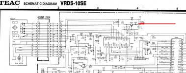
Donc, je reviens sur les schematics disponibles chez TEAC (10 et 25 qui correspondent le mieux au Wadia 16, mécanique Teac CMK 3,2 / laser Sony KSS151A). Ce module d'affichage est relié par des nappes à la carte DAC et à la carte Servo.
En remontant le tout, je m'aperçois que l'un des fils qui relie la carte Servo à la mécanique (fil orange qui relie le connecteur P405 de la carte Servo à la mécanique Teac) est comme "écrasé". Ou comme s'il avait pris un coup de chaud et que sa gaine ait "fondu". Pas facile de tester la continuité mais elle ne tient qu'à un fil. Dans le doute je coupe, soude et gaine. L'endroit de ce défaut sur le fil se situe environ au niveau du condensateur C491 sur le PCB Servo. Aurait-il chauffé et fondu partiellement la gaine ? je ne le saurai pas tout de suite, puisque je pense à cet instant avoir compris l'origine de la panne. Funeste erreur, après remontage complet, sur lequel je fais très attention à ne rien brusquer, surtout les nappes souples de câbles... rien n'a changé. Toujours pareil. Zut.
Je reviens donc sur ce que j'identifie comme l'endroit où se gèrent les commandes du plateau et du moteur, le dénommé U491 qui doit être si on en croit la légende, un CI µPD75212ACW (NEC 4-BIT single-chip microcomputer DIP 64 pins). A priori si c'est lui le coupable (pourquoi ? surtension ? vieillissement ? condensateur de découplage HS ?), pas de problème pour le changer. On en trouve sur eBay à des prix variables, a priori estampillés NEC.
Mais sur la notice d'assemblage officielle Wadia, qui indique comment monter le PCB Servo TEAC et la mécanique associée CMK 3,2, il est très clairement écrit : the Teac mechanism must match the servo board. Et en effet, le n° porté sur la mécanique de mon W16 est exactement le même que celui porté sur le CI µPD75212ACW. Ce CI est-il programmé en fonction de la mécanique associée ? Un échange standard du CI ne serait donc pas fonctionnel ? sur toutes les fonctions ou seulement sur une partie ? Comment savoir ?
Je crois que je vais essayer, après avoir démonté le PCB servo-board (donc quasiment démonté toute la partie gauche du Wadia 16 et le fond...), de dessouder le CI NEC. De souder un adaptateur de bonne qualité DIP 64 pins. Et d'essayer ensuite d'y mettre le fameux µPD75212ACW que j'aurais acheté sur eBay (pas trouvé ailleurs cette référence). On verra bien. J'aurais quand même pensé en même temps à vérifier les condensateurs autour, voire l'oscillateur. On verra bien.
Je vous tiens au courant. Et j'ajouterai quelques photos, c'est plus parlant.
-------------------------------------------------------------------------------------------------
for interested English speakers
I am trying to understand the nature of the problem with my Wadia 16 which I summarize below:
For years everything worked fine (even very well), until one day the "disk" commands stopped working.
Symptoms:
[/ B]
If there is a disc in the machine, and that I turn the player on, then playback starts and goes till the end of the disc, without any problem.
But :
No tray or motor control is working (Stop / Play / Skip / Search / Index / Pause / Open / Close etc ...), either via the remote control or directly on the front (Play / Open 2 buttons).
Every other function of the remote work (volume, source, display on-off, input, mute, insert. The Pause led lights up but it is not paused), so I eliminate a problem on the remote control or on the IR receiver [/ B].
Upon disassembly (almost complete), I did not observe any sign of overheating or oxidation, neither on the Wadia Audio/DAC circuit (the one above, visible when opening the top cover), nor on the Servo PCB Teac (the one below, which requires removing the PCB from above to be accessible). The Key PCB (as described on the pdf of the Teac diagram), i.e. the display PCB - among others) showed some traces of oxidation on the JP1 and JP2 connectors - not sure that the contacts were perfect , therefore deep cleaning. To dismantle this card, it is not just removing 3 screws ... you have to take out the entire front panel. it is feasible but you have to plan an hour anyway.
So I resume. At first I naively thought that the responsible IC could (read: could) be the MAX7219 (which is, as the datasheet says, an 8-Digit LED Display Driver) which happens to be the IC present on the Key PCB. On the Teac notice (of the VRDS T1 or of the VRDS 10 or of the VRDS 25), this IC is supposed to be a µPD7566. Perhaps this is the case on the TEACs but not on the Wadia, which must have its own display card ... But if this MAX7219 is a Led Display driver (and it is for sure), little chance so that it is in connection with the commands of the CD.
So, I come back to the schematics available from TEAC (10 and 25 which best match the Wadia 16, Teac CMK 3.2 mechanics / Sony KSS151A laser). This display module is connected by cables to the DAC PCB and to the Servo PCB.
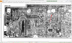
While reassembling the whole, I realize that one of the wires which connects the Servo card to the mechanics (orange wire which connects the P405 connector of the Servo card to the Teac mechanics) is like "crushed". Or as if he got hot and his sheath "melted". Not easy to test for continuity but it hangs by a wire or two. When in doubt I cut, solder and sheath. The location of this fault on the wire is approximately near capacitor C491 on the Servo PCB. Would it have partially heated and melted the sheath? I won't know right away, since I think - at that moment - that I had found the origin of the failure. How wrong, after complete reassembly, on which I am very careful not to rush anything, especially the flexible layers of cables ... nothing has changed. Always the same. Damn.
So I come back to what I identify as the place where the plate and motor controls are managed, the so-called U491 which must be, if we are to believe the legend, a µPD75212ACW IC (NEC 4-BIT single-chip microcomputer DIP 64 pins). A priori if this IC is the culprit (why? Overvoltage? Aging? Decoupling capacitor HS?), no problem to change it. They can be found on eBay at variable prices, a priori stamped NEC.
But on the official Wadia assembly instructions, which shows how to assemble the TEAC Servo PCB and associated CMK 3.2 mechanics, it is very clearly written: the Teac mechanism must match the servo board. And indeed, the number on the mechanics of my W16 is exactly the same as the one on the µPD75212ACW IC. Is this IC programmed according to the associated mechanics? A standard IC exchange would therefore not be functional? on all functions or only on a part? How to know ?
I think that I will try, after having dismantled the servo-board PCB (thus almost dismantled all the left part of the Wadia 16 and the bottom ...), to unsolder the NEC IC. Solder a good quality 64 pin DIP adapter. And then try to put the famous µPD75212ACW that I would have bought on eBay (not found this reference elsewhere). We'll see. I would still have thought at the same time to check the capacitors around, or even the oscillator. We'll see.
I'll keep you informed. And I will add some photos, it's more meaningful.
Thanks for reading, and ready to hear from inspired readers!
English translation below
Bonjour Pierre,
je suis en train d'essayer de comprendre la nature du problème de mon Wadia 16 que je résume ci-dessous :
Pendant des années, tout fonctionne bien (très bien même), jusqu'à un jour où les commandes "disque" ont arrêté de fonctionner.
Symptômes :
S'il y a un disque dans la machine, et que j'allume la machine, alors la lecture démarre, et va jusqu'à la fin du disque, sans aucun problème.
Mais :
Aucune commande du plateau ne fonctionne (Stop/Play/Skip/Search/Index/Pause/Open/Close etc...), que ce soit via la télécommande ou directement en façade (2 boutons Play/Open).
Les autres fonctions de la télécommande fonctionnent (volume, source, display on-off, input, mute, insert. La led Pause s'allume mais il n'est pas en pause), donc j'élimine un problème sur la télécommande ou sur le récepteur IR.
Au démontage (presque complet), je n'observe aucun signe de surchauffe ou d'oxydation, ni sur le circuit de conversion DAC Wadia (celui du dessus, visible dès l'ouverture du capot supérieur), ni sur le Servo PCB Teac (celui du dessous, qui nécessite pour être accessible de démonter le PCB du dessus). Le Key PCB (tel que décrit sur le pdf du schéma Teac), c'est à dire le PCB de l'afficheur - entre autres) présentait quelques traces d'oxydation sur les connecteurs JP1 et JP2, pas sûr que les contacts étaient parfaits, donc nettoyage. Pour le démontage de cette carte, ce n'est pas seulement retirer 3 vis... il faut sortir toute la façade avant. ça se fait mais il faut prévoir une petite heure quand même.
Donc je reprends. Au début je pensais naïvement que le CI responsable pouvait (pouvait) être le MAX7219 (qui est comme le dit le datasheet, un 8-Digit LED Display Driver) qui se trouve être le CI présent sur le Key PCB. Sur la notice Teac (du VRDS T1 ou du VRDS 10 ou du VRDS 25), ce CI est censé être un µPD7566. Peut-être est-ce le cas sur les TEAC mais pas sur le Wadia, qui doit bénéficier de sa propre carte d'affichage... Mais si ce MAX7219 est un Led Display driver (et il l'est), peu de chances pour que ce soit en lien avec les commandes du CD.
Donc, je reviens sur les schematics disponibles chez TEAC (10 et 25 qui correspondent le mieux au Wadia 16, mécanique Teac CMK 3,2 / laser Sony KSS151A). Ce module d'affichage est relié par des nappes à la carte DAC et à la carte Servo.
En remontant le tout, je m'aperçois que l'un des fils qui relie la carte Servo à la mécanique (fil orange qui relie le connecteur P405 de la carte Servo à la mécanique Teac) est comme "écrasé". Ou comme s'il avait pris un coup de chaud et que sa gaine ait "fondu". Pas facile de tester la continuité mais elle ne tient qu'à un fil. Dans le doute je coupe, soude et gaine. L'endroit de ce défaut sur le fil se situe environ au niveau du condensateur C491 sur le PCB Servo. Aurait-il chauffé et fondu partiellement la gaine ? je ne le saurai pas tout de suite, puisque je pense à cet instant avoir compris l'origine de la panne. Funeste erreur, après remontage complet, sur lequel je fais très attention à ne rien brusquer, surtout les nappes souples de câbles... rien n'a changé. Toujours pareil. Zut.
Je reviens donc sur ce que j'identifie comme l'endroit où se gèrent les commandes du plateau et du moteur, le dénommé U491 qui doit être si on en croit la légende, un CI µPD75212ACW (NEC 4-BIT single-chip microcomputer DIP 64 pins). A priori si c'est lui le coupable (pourquoi ? surtension ? vieillissement ? condensateur de découplage HS ?), pas de problème pour le changer. On en trouve sur eBay à des prix variables, a priori estampillés NEC.
Mais sur la notice d'assemblage officielle Wadia, qui indique comment monter le PCB Servo TEAC et la mécanique associée CMK 3,2, il est très clairement écrit : the Teac mechanism must match the servo board. Et en effet, le n° porté sur la mécanique de mon W16 est exactement le même que celui porté sur le CI µPD75212ACW. Ce CI est-il programmé en fonction de la mécanique associée ? Un échange standard du CI ne serait donc pas fonctionnel ? sur toutes les fonctions ou seulement sur une partie ? Comment savoir ?
Je crois que je vais essayer, après avoir démonté le PCB servo-board (donc quasiment démonté toute la partie gauche du Wadia 16 et le fond...), de dessouder le CI NEC. De souder un adaptateur de bonne qualité DIP 64 pins. Et d'essayer ensuite d'y mettre le fameux µPD75212ACW que j'aurais acheté sur eBay (pas trouvé ailleurs cette référence). On verra bien. J'aurais quand même pensé en même temps à vérifier les condensateurs autour, voire l'oscillateur. On verra bien.
Je vous tiens au courant. Et j'ajouterai quelques photos, c'est plus parlant.
-------------------------------------------------------------------------------------------------
for interested English speakers
I am trying to understand the nature of the problem with my Wadia 16 which I summarize below:
For years everything worked fine (even very well), until one day the "disk" commands stopped working.
Symptoms:
[/ B]
If there is a disc in the machine, and that I turn the player on, then playback starts and goes till the end of the disc, without any problem.
But :
No tray or motor control is working (Stop / Play / Skip / Search / Index / Pause / Open / Close etc ...), either via the remote control or directly on the front (Play / Open 2 buttons).
Every other function of the remote work (volume, source, display on-off, input, mute, insert. The Pause led lights up but it is not paused), so I eliminate a problem on the remote control or on the IR receiver [/ B].
Upon disassembly (almost complete), I did not observe any sign of overheating or oxidation, neither on the Wadia Audio/DAC circuit (the one above, visible when opening the top cover), nor on the Servo PCB Teac (the one below, which requires removing the PCB from above to be accessible). The Key PCB (as described on the pdf of the Teac diagram), i.e. the display PCB - among others) showed some traces of oxidation on the JP1 and JP2 connectors - not sure that the contacts were perfect , therefore deep cleaning. To dismantle this card, it is not just removing 3 screws ... you have to take out the entire front panel. it is feasible but you have to plan an hour anyway.
So I resume. At first I naively thought that the responsible IC could (read: could) be the MAX7219 (which is, as the datasheet says, an 8-Digit LED Display Driver) which happens to be the IC present on the Key PCB. On the Teac notice (of the VRDS T1 or of the VRDS 10 or of the VRDS 25), this IC is supposed to be a µPD7566. Perhaps this is the case on the TEACs but not on the Wadia, which must have its own display card ... But if this MAX7219 is a Led Display driver (and it is for sure), little chance so that it is in connection with the commands of the CD.
So, I come back to the schematics available from TEAC (10 and 25 which best match the Wadia 16, Teac CMK 3.2 mechanics / Sony KSS151A laser). This display module is connected by cables to the DAC PCB and to the Servo PCB.
While reassembling the whole, I realize that one of the wires which connects the Servo card to the mechanics (orange wire which connects the P405 connector of the Servo card to the Teac mechanics) is like "crushed". Or as if he got hot and his sheath "melted". Not easy to test for continuity but it hangs by a wire or two. When in doubt I cut, solder and sheath. The location of this fault on the wire is approximately near capacitor C491 on the Servo PCB. Would it have partially heated and melted the sheath? I won't know right away, since I think - at that moment - that I had found the origin of the failure. How wrong, after complete reassembly, on which I am very careful not to rush anything, especially the flexible layers of cables ... nothing has changed. Always the same. Damn.
So I come back to what I identify as the place where the plate and motor controls are managed, the so-called U491 which must be, if we are to believe the legend, a µPD75212ACW IC (NEC 4-BIT single-chip microcomputer DIP 64 pins). A priori if this IC is the culprit (why? Overvoltage? Aging? Decoupling capacitor HS?), no problem to change it. They can be found on eBay at variable prices, a priori stamped NEC.
But on the official Wadia assembly instructions, which shows how to assemble the TEAC Servo PCB and associated CMK 3.2 mechanics, it is very clearly written: the Teac mechanism must match the servo board. And indeed, the number on the mechanics of my W16 is exactly the same as the one on the µPD75212ACW IC. Is this IC programmed according to the associated mechanics? A standard IC exchange would therefore not be functional? on all functions or only on a part? How to know ?
I think that I will try, after having dismantled the servo-board PCB (thus almost dismantled all the left part of the Wadia 16 and the bottom ...), to unsolder the NEC IC. Solder a good quality 64 pin DIP adapter. And then try to put the famous µPD75212ACW that I would have bought on eBay (not found this reference elsewhere). We'll see. I would still have thought at the same time to check the capacitors around, or even the oscillator. We'll see.
I'll keep you informed. And I will add some photos, it's more meaningful.
Thanks for reading, and ready to hear from inspired readers!
@pierrevanraemdonck & @perelman - send Roton a private message via DYIaudio messaging system. He does not read this thread but will be alerted to your incoming message.
To the Wadia 16
I had similar problems with mine to start with. I bought mine which was written off by another workshop as uneconomical to repair.
The tray would not come out.
As always, the first thing was to replace the belts and clean all the microswitches.
Belt replacement is tricky with VRDS but can be done without removing the mechanism.
You have to be careful not to damage the limit (micro)switch when replacing the loading belt though. The best is to just remove it from chassis.
My next problem was that it was unresponsive to commands.
This was because the ribbon cable from display board to the servo board was inserted wrong way round. It will not be the case in your machine, because the fault just occurred one day. But I would spray the sockets at both ends and clean the contacts on the ribbon (even with pencil rubber eraser).
My videos about the Wadia are on my uTube channel, and it shows it mid-repair when I still did not know that the ribbon was reversed, and hence I could not increase the volume to get analogue output:
Wadia 16 mid service. Features, faults and very fresh KSS-151A laser. - YouTube
There is another one about this unit but it is only a sales video, so nothing for you guys there.
Cheers
Roman
Thanks Rockeater from down under
Yes you're right about cleaning the contacts wherever they are. But I unplugged and plugged them quite a few times when disassembling the different PCBs and I guess it acts as cleaning them (at least a little bit).
You're right too when you write that it wouldn't be a reverse plugging of the ribbon (anyone of them) which cause the problem on my device. It had been working well till the problem occurred, and I hadn't opened or changed anything at that time.
So I'm a little bit worried about what could cause this problem to happen.
I've seen on your Youtube video a test cable. I've seen on the Teac brochures that test point too, but I can't see where it is on the PCB... can you help me with that specific point? and what do (can) you measure or test with it?
Thanks again and take care.
Thanks Rockeater from down under
I've seen on your Youtube video a test cable. I've seen on the Teac brochures that test point too, but I can't see where it is on the PCB... can you help me with that specific point? and what do (can) you measure or test with it?
Well, the specific point is R407 on the servo board.
Put your voltmeter on it and it will read a voltage drop across that resistor.
From memory, on that video it was about 1200mV which divided by 22 (Ohm), gives you the current of 54.54mA.
The specification for Sony KSS-151A life, is that it should be replaced when the current increases from the original value by 10mA. So where on the laser head they specify (in the second row) a number of - say - 535, it means, that at the factory it was drawing 53.5mA and with the current currently being drawn of 54.54mA, it has increased by about 1mA or 10% of its useful life.
And that the head should be replaced once the current drawn increases to 64.5mA.
Attachments

My pleasure.Thanks a lot for this truly valuable explanation/information, Roman.
Mean, red probe on one side and black on the other pin of R407?
Yes, that is correct, one probe on each end.
Because you cannot get there with multimeter, you have to - as I did - solder some wire and bring them out.
This goes for every Sony pickup where they print the value of current at factory and it usually is 22 Ohm resistor.
Hi @perelman ,Hi pspentax, I've got a few of them, allow me to send you the docs via PM or I'll post them in the thread? tell me. Cheers from France.
Thanks for your help, you can send by PM or post here, it’s up to you.
Cheers,
Pedro
- Home
- Source & Line
- Digital Source
- I have Wadia 16 and Krell Schematics